


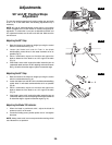
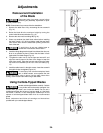
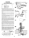
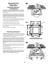
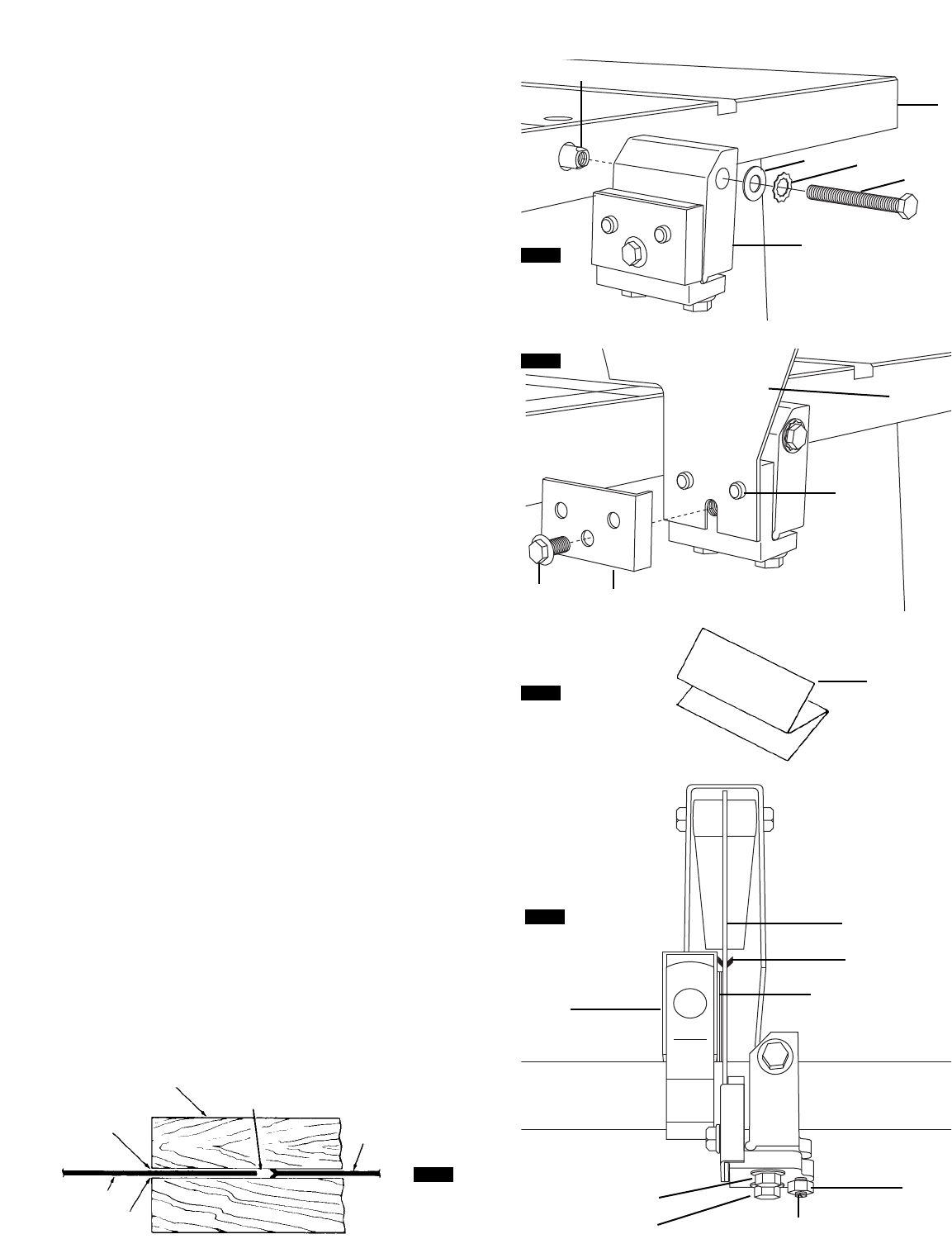
Attaching Blade Guard
1
. From among the loose parts, locate the following hardware
(
Fig. 20).
ITEM DESCRIPTION QTY.
6 Blade Guard and Spreader 1
13 Spreader Support Assembly 1
14 Flat Washer 1
15 Lockwasher (1/4" External) 1
1
6 Hex Bolt (1/4-20 x 2") 1
Note: Adjustments to the following bolt & screws can be done
using the small end of arbor wrench or a 10 mm wrench.
1
. Align flats on inside of speader support assembly
1
3
w
ith flats
on end of pivot rod
7 located on back side of table 8 and
securely fasten to pivot rod
7 using the 1/4-20 x 2" long hex bolt
16, 1/4" external tooth lockwasher 15 and flat washer 14
(Fig. 20).
2. Remove flanged hex bolt
21 and remove clamping plate 22
(Fig. 21).
3. Position spreader
6 over bumps 9, then position clamping
plate
22 as shown over bumps 9 and securely tighten flanged
hex bolt
21 (Fig. 21).
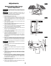
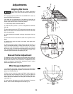
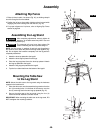
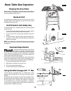
4. Loosen hex nut
20 and back out set screw 19 three turns with
a flat tip screwdriver. Loosen flanged hex bolts
23 three turns
with the 10 mm open end wrench (Fig. 23).
5. Raise the saw blade to maximum height and make sure it is
perpendicular to the table.
6. Place rip fence
2 on table and CAREFULLY move fence 2
against the blade so that it is parallel to the blade, and just
touches tips of saw teeth
10. The guard and ANTIKICKBACK
PAWL of the Spreader Assembly have to be lifted and rested on
top of the rip fence in order to bring the fence in contact with the
blade. Lock fence
2 and make sure the blade at front and back
is still touching the fence (Fig. 23).
7. Using the fence
2 as a guide, align the spreader 6 with the
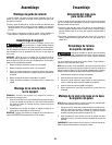
plane of the sawblade. Since the spreader
6 is thinner by
approximately three thicknesses of paper on each side than the
width of the blade’s KERF
11 (Fig. 24) you must make a
temporary paper “spacing gauge”. Make two folds in a small
piece (6" x 6") of ordinary newspaper making three thicknesses
(Fig. 22).
8. Insert folded paper
18 between SPREADER and FENCE.
Hold spreader
6 by hand firmly against fence 2 while finger
tightening the hex bolts
23 then lightly tighten the set screw 19
(Fig. 23).
9. Release the hand hold of the spreader and fence and recheck
the spreader alignment with the blade. Readjust if necessary.
IMPORTANT:
The plane of the Spreader 6 must always be IN
LINE with the plane of the sawblade 10 when blade is
perpendicular to the table or at any bevel angle .
10. After proper alignment adjustment is made, tighten hex nut
20 and securely tighten flanged hex bolts 23.
11
10
12
6
12
FIG. 23
FIG. 24
WORK
BOIS
MADERA
LOOKING DOWN ON SAW
VUE DE DESSUS
VISTA HACIA ABAJO SOBRE LA SIERRA
FIG. 20
FIG. 21
38
.
Assembly
14
15
16
13
6
7
8
21
22
9
FIG. 22
18
20
19
23
23
2
6
18
10