


26
.
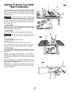
If you are making a rip type cut in thinner materials, the facing
should be attached to the fence so that the bottom edge touches
the top surface of the table. In this situation, the facing must be
lower than the fence. This will prevent thin material from sliding
under the rip fence.
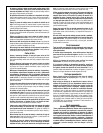
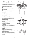
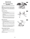
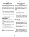
When positioning fence
14 for maximum rip
cutting (without table extension), make sure side
o
f fence housing
(
a)
i
s even with the side edge of the table
2.
Do
not make rip cuts or dado cuts beyond this position because the
fence can not be properly locked. Maximum rip cut capacity is
1
0 3/4 inches (Fig. 5).
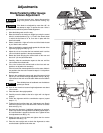
15. BLADE GUARD
Protects the operator, and must always be in place and working
properly for all thru-sawing cuts. That is all cuts whereby the blade
cuts completely through the workpiece.
16. TABLE INSERT
Is removable for removing or installing blade or other cutting tools.
For your own safety, turn switch “OFF” and
remove plug from power source before removing
insert.
To remove the insert:
A. Lower the blade below the table surface.
B. Raise blade guard.
C. Remove insert screws and lift insert from pocket in table.
Never operate the saw without the proper insert in place. Use the
saw insert when sawing, and the dado insert when dado cutting.
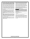
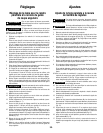
17. MITER GAUGE
Head can be locked in desired position for crosscutting or mitering
by tightening the lock handle. ALWAYS SECURELY LOCK IT
WHEN IN USE.
Notches are provided in the miter gauge
17 for attaching an
AUXILIARY FACING
(b) to make it easier to cut longer pieces. Be
sure facing does not interfere with the proper operation of the saw
blade guard.
Select a suitable piece of smooth straight wood 3/4" thick, drill two
holes through it and attach it with two round head #10 or #12 round
head screws 1-1/4" long (
c) (Fig. 7).
NOTE: When bevel crosscutting, attach facing so that it extends to
the right of the miter gauge and use the miter gauge in the groove
to the right of the blade.
Getting To Know Your Table
Saw (Continued)
WARNING
!
WARNING
!
b
c
FIG. 7
17
15
Maximum 10 3/4”
FIG. 5
14
2
a
16
FIG. 6
17