


FIG. 19
36
.
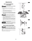
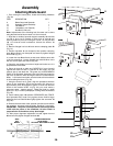
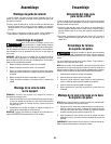
Aligning Rip Fence
T
o prevent personal injury, always disconnect
plug from power source before making any
adjustments.
The rip fence must be parallel with the SAWBLADE in order to
prevent KICKBACK when ripping.
Y
our table saw is equipped with a Self-Aligning, Quick-Set rip
fence. Once the adjustments below have been made, the rip fence
will self align when the fence is locked into position.
1. To move the rip fence, raise lock handle
1.
2. Slide fence
2 by handle 1, until it is alongside the sawblade
(Fig. 18).
The fence should touch the “SET” teeth at the front and rear of the
blade. If fence does not touch the teeth at front and rear of blade
follow the steps below.
3. Loosen the two hex screws
3 on the top front section of the rip
fence.
4. Move fence
2 until it touches the teeth and is parallel to the
blade.
5. Hold fence in place and lower lock handle, then tighten hex
screws (Fig. 18).
6. Clamp rip fence to check if it holds securely at front and rear. If
rear is not clamped securely, unclamp fence and turn rear clamp
adjustment screw
4 clockwise for increased clamping. Try clamping
the fence to verify if it self aligns and clamps tightly at the front and
rear. Overtightening of the rear clamp adjustment screw
4 will
cause the rip fence to be non-self aligning (Fig. 18).
Manual Pointer Adjustment
The distance of the rip fence body from the blade when ripping on
the right side of the blade is determined by lining the pointer
5 with
the desired dimension on the scale
6. If an adjustment to the
pointer is necessary, loosen pointer adjustment screw
7, adjust
pointer
5 and tighten screw 7 (Fig. 18).
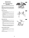
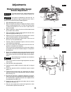
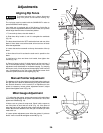
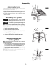
Miter Gauge Adjustment
1. To adjust the miter gauge, loosen miter gauge lock handle 8 and
set the miter gauge body so the pointer
11 is at the 90° mark, then
tighten lock handle
8 (Fig. 19).
2. Make a cut on a piece of scrap wood. Check it with a square to
see if the piece of wood was cut at 90
°
(Fig. 19). If the piece of
wood was not cut 90
°
, adjust the miter gauge body
9, tighten lock
handle
8 and make additional cuts until you are certain you have
made a 90
°
cut.
3. Loosen pointer adjustment screw
10 so the pointer 11 points to
the 90° mark on scale
12 and tighten screw 10 (Fig. 19).
Adjustments
WARNING
!
9
8
10
11
12
1
1
0
23
4
2
2
2
2
2
3
0
23
2
2
2
1
2
2
2
4
1
1
10
FIG. 18
1
4
2
3
1
10
23
4
6
5
7