


For Machines Mfg. Since 5/11 14" TURN-X
®
Toolroom Lathe
-25-
PREPARATION
In addition to the reservoirs, we also recommend
that you lubricate all other points on the
machine at this time. This can be accomplished
by following the maintenance schedule on
Page 64.
Note: If this lathe was shipped with oil in the
reservoirs, do not change that oil until after the
test run and spindle break-in procedures.
Adding Coolant
Add the coolant of your choice now. For detailed
instructions on where the coolant tank is located
and how to add fluid, refer to Coolant System
Service on Page 71.
Power Connection
Once your machine is set up and assembled as
previously described in this manual, it is ready to
be connected to the power source.
Note About Extension Cords: Using an
incorrectly sized extension cord may decrease the
life of electrical components on your machine.
Refer to Extension Cords on Page 18 for more
information.
Note About 3-Phase Power: DO NOT use a static
phase converter to create 3-phase power—it can
quickly decrease the life of electrical components
on this machine. If you must use a phase
converter, only use a rotary phase converter
and connect the manufactured leg to the correct
power connection terminal, shown in the wiring
diagram on Page 90.
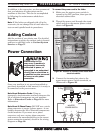
To connect the power cord to the lathe:
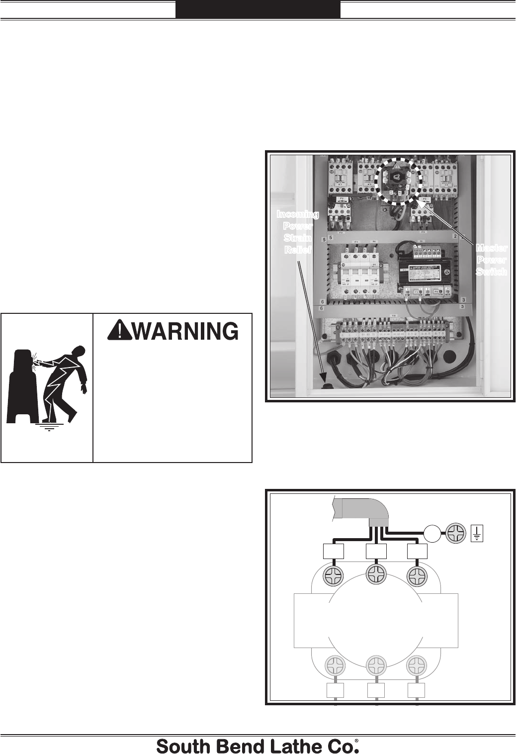
1. Make sure the master power switch is
turned to the OFF position, then open the
electrical cabinet door.
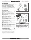
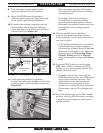
2. Thread the power cord through the strain
relief, and up to the master power switch
shown in Figure 21.
Electrocution or fire
may occur if machine is
ungrounded, incorrectly
connected to power, or
connected to an undersized
circuit. Use an electrician or
a qualified service personnel
to ensure a safe power
connection.
Figure 21. Location to connect power inside main
electrical cabinet.
Incoming
Power
Strain
Relief
Master
Power
Switch
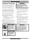
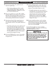
3. Connect the incoming hot wires to the
upper master power switch terminals, as
illustrated in Figure 22.
To Plug
Hot
L3
L2
L1
Gn
Ground
5
6
31
42
MASTER
POWER SWITCH
Hot
Hot
Figure 22. Power connection at master power switch.