


For Machines Mfg. Since 5/11 14" TURN-X
®
Toolroom Lathe
-5-
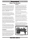
INTRODUCTION
Refer to Figures 2–7 and the following
descriptions to become familiar with the basic
controls of this lathe.
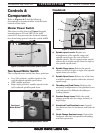
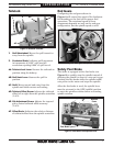
Master Power Switch
The rotary switch shown in Figure 2 toggles
incoming power ON and OFF to the lathe
controls. It also prevents the electrical cabinet
door from being opened when the switch is ON.
Controls &
Components
Figure 2. Location of the master power switch.
Main Power
Switch
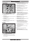
A. Spindle Speed Charts: Display the
arrangement of the spindle range and
spindle speed levers for each of the 16
spindle speeds. The two-speed motor switch
selects the available speeds from the high or
low spindle speed chart.
B. Spindle Range Lever: Selects the speeds
shown in the left (high) or right (low) spindle
speed chart to be active.
C. Spindle Speed Lever: Selects one of the four
available spindle speeds within the selected
speed range.
D. Threading and Feed Charts: Displays the
necessary configuration of the gearbox levers
and end gears for different threading or
feeding options.
E. Gearbox Range Lever: Shifts the quick-
change gearbox into low range, neutral, or
high range.
F. Headstock Feed Direction Lever: Controls
the direction that the leadscrew and feed rod
rotate.
G. Quick-Change Gearbox Levers: Control the
leadscrew and feed rod speed for threading
and feed operations.
Two-Speed Motor Switch
The two-speed motor switch has three positions:
• Low(leftposition),enablesspeedsinthe
right headstock spindle speed chart
• OFF(middleposition)
• High(rightposition),enablesspeedsinthe
left headstock spindle speed chart
Figure 3. Location of the two-speed motor switch.
Two-Speed
Motor Switch
Headstock
Figure 4. Headstock controls.
G
F
D
C
E
A
B