


For Machines Mfg. Since 5/11 14" TURN-X
®
Toolroom Lathe
-79-
SERVICE
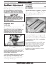
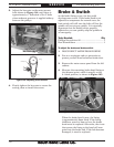
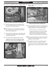
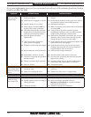
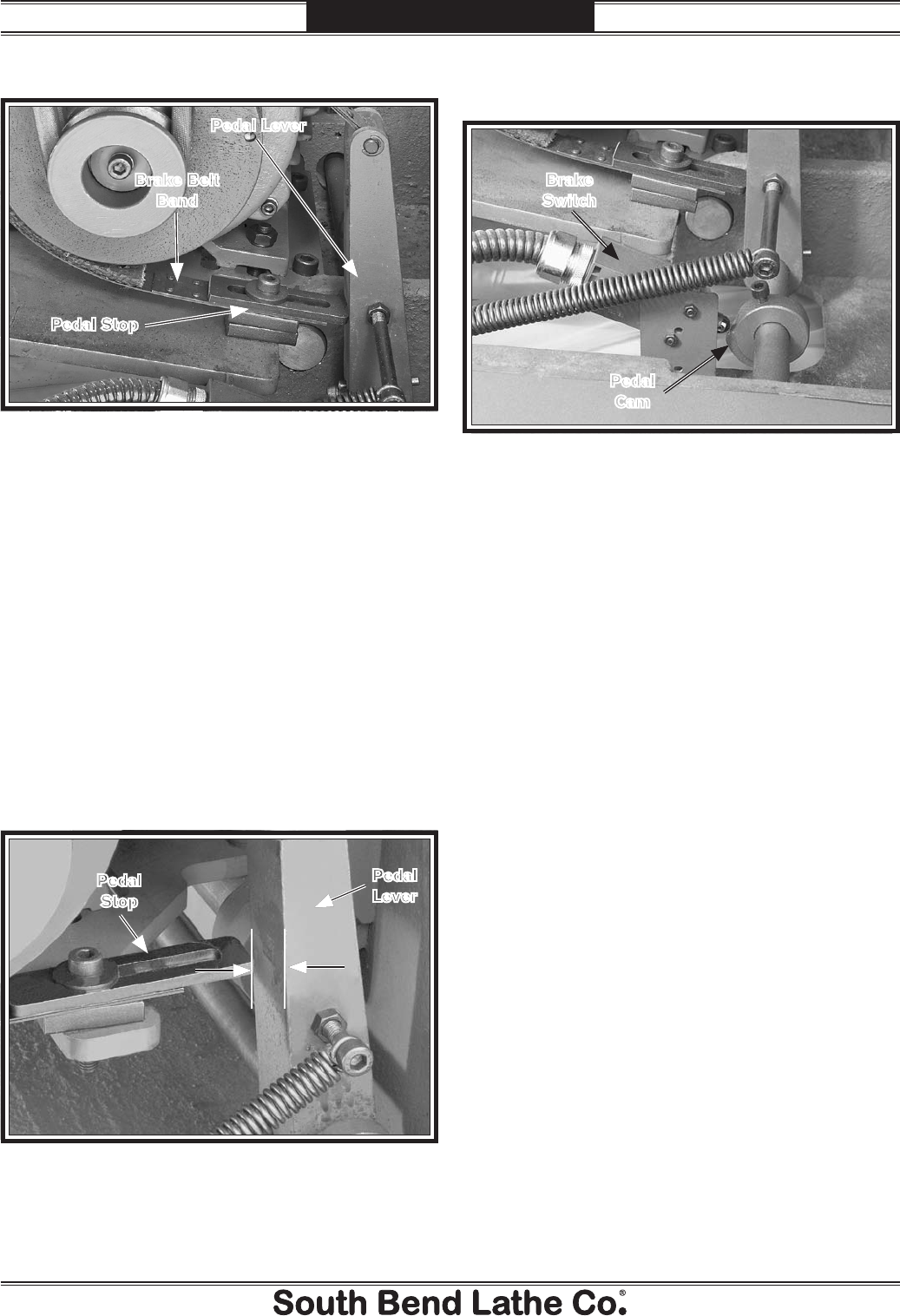
5. Remove the pedal stop shown in Figure 126.
6. Move the brake band to the right one hole,
and re-install the pedal stop, tightening the
cap screw until it is just snug.
Note: If installing a new brake band, install the
cap screw so there is one hole to the left for
future brake adjustment.
7. Firmly push the pedal lever to the right until
it stops and the brake band is fully clamped
around the brake hub.
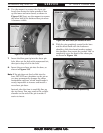
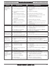
8. Tap the pedal stop into position so there
is approximately a 25mm gap between the
pedal lever and the stop (see Figure 127),
then firmly tighten the pedal stop cap screw.
Figure 126. Brake belt adjustment components.
Pedal Stop
Pedal Lever
Brake Belt
Band
10. Push the pedal lever down to verify that the
cam lobe pushes the brake switch plunger in.
When pushed in, the switch should click.
— If the switch does not click, loosen the
switch mounting screws, push the brake
pedal all the way down, and move the
switch closer to the lobe until it clicks.
Secure the switch in place at this location.
Note: In the released position, there should be an
approximate 3mm gap between the switch
plunger and the cam lobe.
11. Re-install the motor access panel, connect
the lathe to power, then test the brake
pedal. If you are not satisfied with the brake
performance, repeat this procedure until you
are.
Figure 127. Brake pedal travel adjustment.
Pedal
Lever
Pedal
Stop
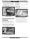
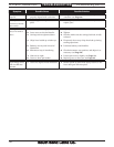
9. Locate the brake switch shown in
Figure 128.
Figure 128. Brake switch and pedal cam.
Brake
Switch
Pedal
Cam