


For Machines Mfg. Since 5/11 14" TURN-X
®
Toolroom Lathe
-27-
PREPARATION
3. Clear away all tools and objects used during
assembly, lubrication, and preparation.
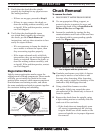
4. Make sure that the chuck and jaws, if
installed, are secure (refer to Chuck and
Faceplate Mounting on Page 32).
Note: If a chuck is not installed on the lathe, you
do not need to install one for this test.
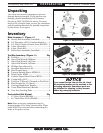
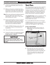
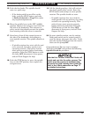
5. Push the STOP button on the control panel
(see Figure 24), and point the coolant nozzle
into the chip pan.
Figure 24. Control panel.
Power
Lamp
STOP
Button
Jog
Button
Cutting Fluid
Pump Switch
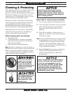
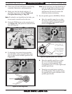
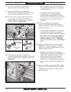
6. To disengage the quick-change gearbox
from the drive train, move the feed range
lever to the neutral (middle) position (see
Figure 25).
Figure 25. Feed range lever.
Low
Neutral
Feed Range Lever
High
Feed
Range Lever
Note: In the next step, use the chuck key to
rock the chuck back-and-forth so that
the gears will mesh as you make the
adjustments. Be sure to remove the
chuck key before continuing.
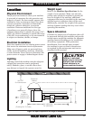
7. Set the spindle speed to 50 RPM as follows:
a. Move the spindle range lever so that
the arrow on top of its hub is pointing
toward the right-hand spindle speed
chart (see Figure 26).
b. Move the spindle speed lever so that
the "A" on its hub is directly under
the arrow on the headstock. This
corresponds to the "A" in the right-hand
spindle speed chart.
c. Turn the two-speed motor switch to
the LOW position. This enables all the
low speeds in the green columns of the
spindle speed charts.
A
B
C
D
Spindle Range
Lever Pointing
To The Right-
Hand Speed
Chart
Spindle Speed
Lever Set To
“A” (50 RPM)
Figure 26. Spindle speed set to 50 RPM.
Speed
Lever
Spindle Range
Lever