


For Machines Mfg. Since 5/11 14" TURN-X
®
Toolroom Lathe
-53-
OPERATION
Depending on the combined configuration of
the headstock feed direction lever and the
apron feed direction knob, the actual direction
of power feed may be different from the
printed indicators on the machine!
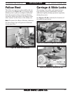
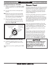
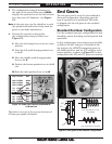
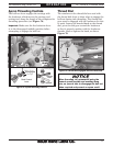
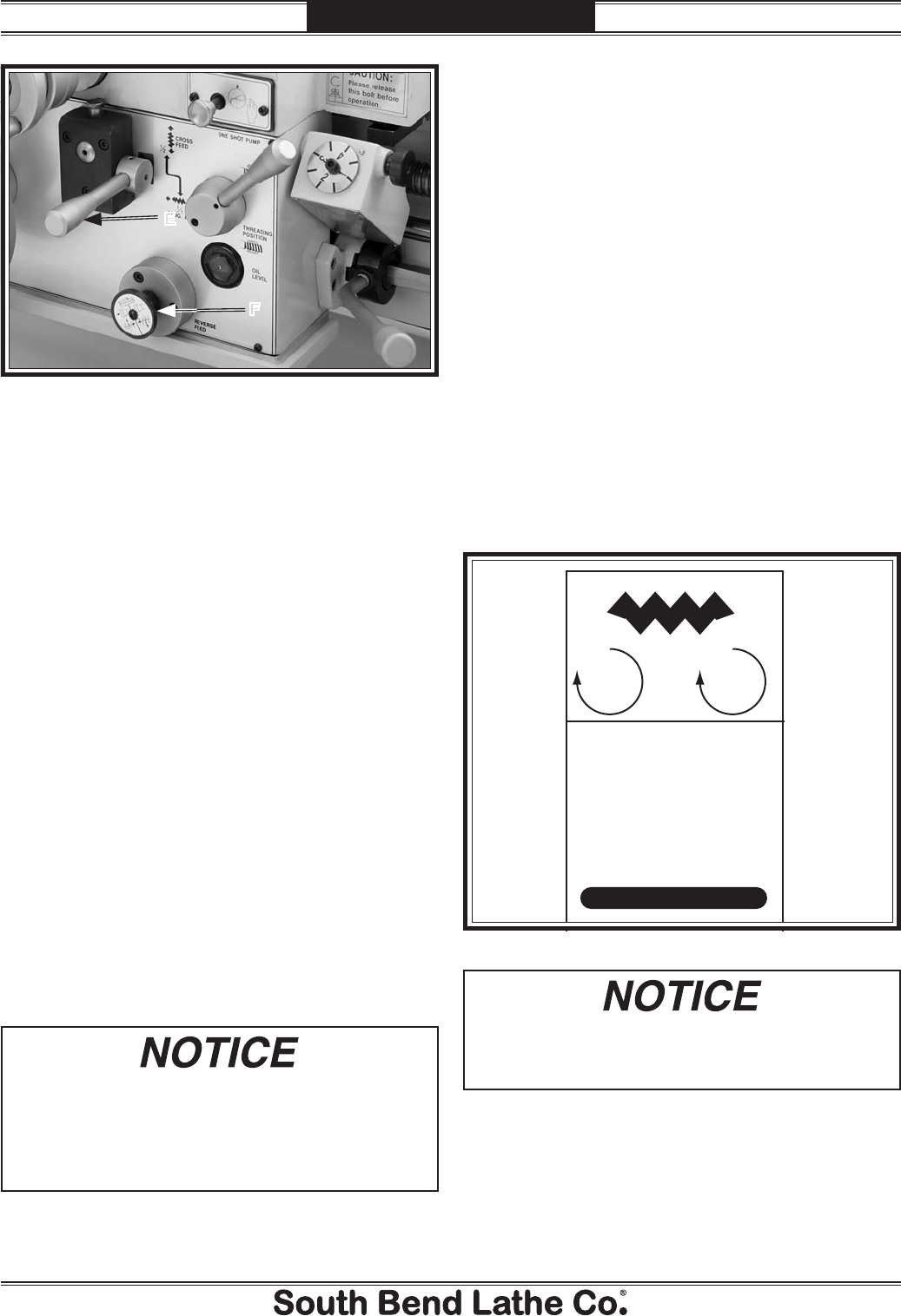
E. Feed Selection Lever: Directs the power feed
to either the cross slide or the carriage.
When the lever is down and the indent pin
is pointing up, the cross slide is selected.
Conversely, when the lever is up and the pin
is pointing down, the carriage is selected.
In the middle position, the apron gears are
disengaged from the feed rod and neither
component will move.
Note: When using this lever, you may need
to slightly rotate the handwheel of the
component you are trying to engage, so that
the apron gears can mesh.
F. Apron Feed Direction Knob: Changes the
feed direction when the lathe is running.
The advantage of this knob is that you can
quickly reverse power feed direction while
the spindle is rotating—without having to
turn the lathe off, waiting until the spindle is
stopped, then using the feed direction lever
on the headstock.
When using power feed to move the cross
slide, the feed rate is
1
⁄2 the value stated in
the feed rate chart.
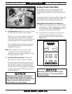
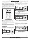
Setting Power Feed Rate
The feed rate chart on the upper right of the
headstock face displays the settings for the
headstock feed controls for metric and inch feed
rates.
Using the controls on the lathe, follow along with
the example below to better understand how to
set the lathe for the desired power feed rate.
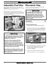
Setting Power Feed Rate of 0.18mm/rev
1. Make sure the end gears are in the standard
configuration, which is applicable for general
feed operations (refer to End Gears on the
next page for detailed instructions).
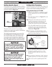
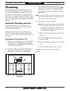
2. Locate the line in the feed rate chart that
lists the setting for 0.18mm of feed per
revolution of the spindle, as illustrated in
Figure 72.
Figure 72. Feed rate chart.
.050 LCT1W .002
.055 LCT2W .0022
.065 LCT4W .003
.085 LCT8W .0033
.10 LCS2W .004
.13 LCS4W .005
.18 LCS8W .007
.22 LCR3W .009
.28 LCR4W .011
.35 LCR8W .014
.44 LCS8X .017
.55 LCR2X .022
.68 LCR3X .027
.85 LCR8X .033
1.2 HCS2X .047
1.4 HCS4X .055
1.7 HCS8X .067
mm
in.
Figure 71. Apron power feed controls.
E
F