


1 –Pump 9-Station Controller Chapter 3: Installation 16 of 38
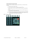
Connecting the Control Panel to Vacuum Hoppers
Note: Wire size depends on control voltage, distance, number of vacuum hoppers,
and the number of wires in each raceway. Consult a qualified electrician.
1. On 24 VDC control voltage systems, run a common +24 VDC wire and a common 0
(zero) VDC wire from the controller to each vacuum hopper in the system.
2. On all systems, run two wires to each vacuum hopper: one each from the controller to
the Bin-Full switch (LS) and to the Atmospheric/Sequence-T solenoid (SOL) valve.
3. Properly ground each hopper to reduce static build up generated by material
conveying.
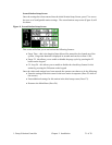
Connecting the Control Panel to the Pump Package
1. Wire the pump package motor starter coil (M) to the terminal provided in the control
panel enclosure.
2. Wire the pump package vacuum relief valve solenoid (10 SOL) to the terminal
provided in the control panel enclosure.
3. Wire the pump package vacuum switch (VS) to the terminal located in the control
panel enclosure.
4. On vacuum pumps with implosion filter cleaning, wire the clearing valve (11 SOL)
and sealing valve (12 SOL) solenoids.
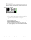
5. On vacuum pumps with compressed air filter cleaning, wire the blowback solenoid
(11 SOL) to the terminal located in the control panel enclosure.
6. Wire the pump package motor overload to the terminal provided in the control panel
enclosure.
7. On 24 VDC control voltage systems, run a common +24 VDC wire and a common 0
(zero) VDC wire from the controller to each pump package in the system.