


Appendix E: Performance Verification
VX4801 Programmable Digital I/O Module
A–21
34
18
1
Byte 3 LSB
Byte 2 MSB
Byte 5 LSB
GND
Byte 0 LSB
DAK
6
DAV
5
GND
GND
GND
134
39
50
33
17
1
14
25
13
8
Byte 4 LSB
DRd
Byte 2 Tri-St
Byte 1 Tri-St
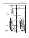
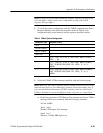
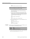
VX4801 Slave ModuleVX4801 Under-test
Byte 0 Tri-St
Byte 5 Tri-St
Byte 4 Tri–St
Byte 3 Tri-St
RFD
17
33
DB-50 MaleDB-50 Male
DB-25 Male
18
Byte 3
Byte 1
Byte 2
50
Allow approximately 6”
length of interconnect
wire between modules.
Figure 4: Loop-Back Cable Assembly (View of Solder Side)