


Appendix E: Performance Verification
A–26
VX4801 Programmable Digital I/O Module
ibrd 0
(Observe: VX4521 Slot 0 indicates S in 2nd digit)
NOTE. The zero length read serves to un-address the Slot 0 controller which
allows it to detect the VXIbus interrupt and assert the SRQ.
b. Check that the FAILED light on the VX4801-device-under-test is on and
that the VX4521 displays an S in the second digit of the front panel
indicating an SRQ pending.
c. With the following commands, perform a serial poll with the VX4801
and verify a response of 40 hexadecimal which indicates that it was the
interrupting device. Also, verify that the VX4521 Slot 0 controller SRQ
is no longer asserted. Finally, perform a second serial poll and observe a
response of 0, indicating no interrupt pending:
ibrsp
(Observe: VX4521 no longer displays S)
ibrsp
(Observe: VX4801 response = 0; interrupt cleared)
d. Perform a Status Query (ASCII) and verify that the ERR light is off, and
then read the error message:
ibwrt "qa"
(Observe: VX4801 ERR light is off)
ibrd 100
(Observe: SYNTAX ERROR.. )
This test sequence verifies that each eight bit port (6) of the VX4801 can provide
both active high and low TTL/CMOS inputs and outputs.
Equipment
Requirements
Loop-back assembly (item 3)
Prerequisites All prerequisites listed on page A–20
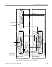
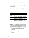
1. Attach the loop-back assembly as shown in Figure 4, which connects the odd
bytes to the even bytes respectively (0 to 1, 2 to 3, 4 to 5).
TTL/CMOS I/O