


Appendix E: Performance Verification
VX4801 Programmable Digital I/O Module
A–27
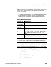
2. Perform a self test and query for any error codes (in ASCII format) with the
VX4801 device-under-test and the Slave VX4801:
ibfind Slave
ibwrt "s;qa"
ibrd 100
(Observe: NO ERRORS)
set VX4801
ibwrt "s;qa"
ibrd 100
(Observe: NO ERRORS)
NOTE. If at any time in this procedure you do not observe the result expected,
check the front panel error light and/or perform an error Status Query (ibwrt
“qa”<cr> ibrd 100<cr>). No additional commands will be accepted until an
error condition is cleared.
3. Verify the odd byte data inputs and the even byte data outputs with the
following steps:
a. Reset the VX4801 to its power-up state and then set its mode for the odd
bytes (1, 3, 5) to be active low inputs, for the even bytes (0, 2, 4) to be
active high outputs loaded with a Load Output value of 55, and set the
tri-state function to be inactive (* => all bytes, i => inactive):
set VX4801
ibwrt "r;m135iL024oh;L024d55;t*i"
b. Perform an input of all bytes and verify a response of 55AA55AA55AA:
ibwrt "i*"
ibrd 100
(Observe: 55AA55AA55AA)
c. Repeat the previous test with the logic sense reversed; i.e. odd bytes (1,
3, 5) set to active high and the even bytes set to active low. Verify the
complementary response:
ibwrt "m135ih024oL"
ibwrt "i*"
ibrd 100
(Observe: AA55AA55AA55)