


Appendix E: Performance Verification
A–28
VX4801 Programmable Digital I/O Module
4. To verify the even byte data inputs and the odd byte data outputs, reset the
VX4801 to its power-up state and then set its mode for the even bytes (0, 2,
4) to be active low inputs, for the odd bytes (1, 3, 5) to be active high
outputs loaded with a Load Output value of 55, and set the tri-state function
to be inactive. Perform an input of all bytes and verify an AA55AA55AA55
response and then reverse the logic sense of the even and odd bytes and
verify the complementary response of 55AA55AA55:
ibwrt "r;m024iL135oh;L135d55;t*i"
ibwrt "i*"
ibrd 100
(Observe: AA55AA55AA55)
ibwrt "m024ih135oL"
ibwrt "i*"
ibrd 100
(Observe: 55AA55AA55AA)
This test sequence verifies that the internal tri-state commands and the external
tri-state signals are functioning properly for each I/O byte.
NOTE. Each I/O signal has an internal 22 kW pull-up to +5 V which will appear
as a high logic level when the in tri-state mode.
Equipment
Requirements
Loop-back assembly (item 3)
Prerequisites All prerequisites listed on page A–20
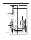
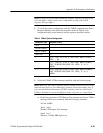
1. Install the loop-back assembly on the VX4801 under-test and the slave
VX4801 as shown in Figure 4.
2. Verify the internal tri-state command with the following steps:
a. Reset the VX4801 to its power-on default state (all bytes initially
tri-stated). Then set its mode for the odd bytes to be active high inputs
and for even bytes to be active high outputs with a Load Output value of
00. Finally, leave the even (output) bytes tri-stated, but set the odd
(input) byte tri-states to be inactivate. Perform an input of all bytes and
verify that the even bytes are in tri-state mode and not driving the odd
byte inputs (odd inputs not pulled low):
set VX4801
Tri-State Function