


Appendix E: Performance Verification
A–24
VX4801 Programmable Digital I/O Module
Self Test
The VX4801 includes a built-in self test function (BITE) which is automatically
executed each time the power is turned on and when the Internal Self Test (S)
command is issued. BITE uses internal routines and circuitry to confirm basic
I/O functionality. No external test equipment is required.
During self test, all outputs are set to a high impedance (tri-state) mode and then
internal loop-back circuitry and test patterns are used to verify all I/O channels.
In addition to BITE, front panel indicator lights display the current status of
power, the assertion of SYSFAIL*, backplane cycles, data handshake signals,
and individual I/O data bits for each byte. The Query command may also be used
at any time during operation to determine the current state of the module.
Following the VXIbus system startup sequence, the green PWR light on the
VX4801 front panel indicates that the self test has passed and that the +5 V
power supply is operational. If the +5 V power supply fails, or its fuse opens, the
PWR light will be off, the FAILED light will be on, and SYSFAIL* will be
asserted indicating a module failure.
NOTE. If you experience an error indication from the Slot 0 Resource Manager,
the VX4801-under-test, or other VXIbus module, investigate and correct the
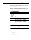
problem before proceeding. Common items to check are logical address conflicts
(primary and secondary; see Table 3), breaks in the VXIbus daisy chain signals,
improper seating of a module, loose GPIB cable, improperly set Slot 0 single-
step switch, or loose or blown fuses.
Performance Verification Tests
The order of execution of this procedure has been chosen to minimize system
setup and functional dependency. Because some tests rely on the success of their
predecessors, it is recommended that you perform all sequences in order.
This sequence verifies that the VX4801 configures correctly and
communicates
properly with your GPIB system controller.
Equipment
Requirements
No additional test equipment is required for this sequence.
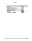
Prerequisites All prerequisites listed on page A–20
VXIbus Interface