


10
Other Features
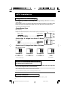
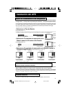
7. DC Input Terminals
The terminals' wing nuts secure the wires leading from your external battery. Connect a battery or
system of batteries that will ultimately combine to provide your APS with 12V DC and your equipment
with an adequate amp hour capacity. For best connection, use soldered lugs on your battery cable.
See Battery Selection section for more information.
8. AC Receptacles (NEMA 5-15R)
These receptacles allow connection of equipment designed to run on 230 VAC 50/60 Hz. power.
APS INT 512 models may require receptacle adapters (Universal Adapter included see Diagram
10.1, p. 48) to connect equipment to the APS.
9. AC Line Cord (NEMA 5-15P fixed or detachable)
Plug the cord into a 230V, 50/60 Hz. outlet. DO NOT plug the cord into the APS’s AC receptacles.
The APS INT 512 features an IEC-320 male plug and a detachable IEC-320 female to NEMA 5-15P
male cord set. Note the polarity of the plug in Diagram 10.2, p. 48.
10. Resettable Circuit Breaker
The circuit breaker protects your APS against damage due to output overload. Remove overload.
Wait 1 minute. Reset circuit breaker.
11. Remote “ON/OFF” Connector
This allows for remote APS control using user-supplied wire and 2-position switch. The connector
accepts a 3.5 mm 2-wire miniature phone plug. Note: The user-supplied remote switch can only
control APS operation when the APS “OPERATING MODE” switch is in the “CHARGE-ONLY”
position. The remote switch can only transfer between the “CHARGE-ONLY” and “AUTO” modes.
After completing a remote connection, determine which position is the “CHARGE-ONLY” mode and
which position is the “AUTO” mode for your particular switch. The position on your remote switch
that causes the green “LINE” indicator light to flash intermittently is the “CHARGE-ONLY” mode
position.
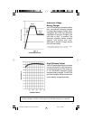
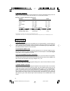
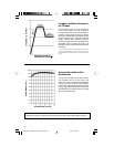
6. “BATTERY HI/MED/LO”
These three lights will turn ON in several sequences to show the approximate charge level and
voltage of your connected battery bank and alert you to several fault conditions:
BATTERY CHARGE INDICATION (Approximate)
Indicator Capacity Volts
Green 91% - Full 12.0 - 16.0
Green & Yellow 81% - 90% 11.8 - 12.0
Yellow 61% - 80% 11.6 - 11.8
Yellow & Red 41% - 60% 11.3 - 11.6
Red 21% - 40% 11.0 - 11.3
— 1% - 20% 10.0 - 11.0
Flashing Red 0% (Inverter shutdown) <10.0
All lights “Slow” Flash* Excessive discharge <8.0
All lights “Rapid” Flash** Overcharge >16.0
* Approximately 1/2 second on, 1/2 second off. See Troubleshooting section.
** Approximately 1/4 second on, 1/4 second off. May also indicate a battery charger fault exists. See Troubleshooting section.
200002089 APS Manual 230 Volt Version.p65 5/31/00, 4:30 PM10