


4
APS Installation
Electrical Connection
Plug APS INT 512 models into outlets providing 230V AC, 50 or 60 Hz. power.
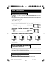
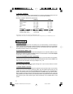
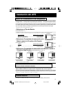
Configuration DIP Switch Settings*
(See Diagram 1, p. 46. Note: 1.1 is a closeup of the Configuration Dip Switches. 1.2 is “front”,
1.3 is “rear”).
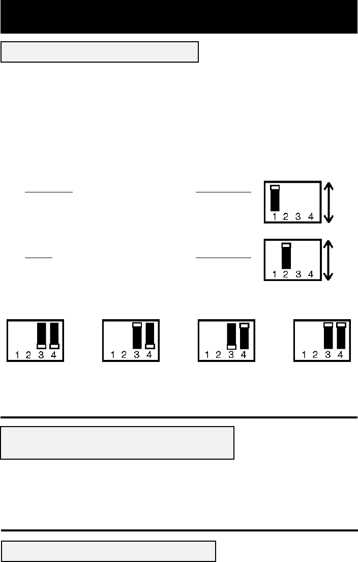
Using a small tool, set the 4 Configuration DIP Switches (located on the bottom of your APS) to select
battery type and set the voltage range outside of which your APS will switch to battery power.
* Select before permanently mounting your APS.
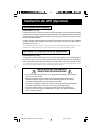
• Select Battery Type
(DIP Switch #1)
CAUTION: The Battery Type DIP Switch setting must match the type of batteries you connect or your batteries may be degraded or
damaged over an extended period of time. See “Battery Selection,” page 6 for more information.
Battery Type Switch Position
Gel Cell (Sealed) Battery ................................. Front
Wet Cell (Vented) Battery ................................ Rear**
• Select High AC Voltage Point Switch To Battery
(DIP Switch #2)
Voltage Switch Position
276V.................................................................. Front
257V.................................................................. Rear**
• Select Low AC Voltage Point Switch To Battery
(DIP Switches #3 & #4)
** Factory default settings.
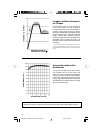
APS INT 512 Conversion from 50 to 60 Hz.
For Qualified Service Personnel Only*
(See Diagram 2, p. 46. Note: 2.1 is the “adjustment resistor” located in the upper right-hand
corner of the component side of the circuit board).
To permanently convert the APS INT 512 to 60 Hz., qualified service personnel should open the APS
case, locate the resistor on the circuit board and remove it.
* Turn your APS OFF and disconnect from the wall outlet before 60 Hz conversion.
144V
#4 Rear
& #3 Rear**
162V
#4 Rear & #3 Front
181V
#4 Front & #3 Rear
200V
#4 Front & #3 Front
Wet
Cell
Gel
Cell
257V
276V
Rear
Front
Rear
Front
Rear
Front
Rear
Front
Rear
Front
Rear
Front
200002089 APS Manual 230 Volt Version.p65 5/31/00, 4:30 PM4