


English
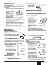
Flushing the Unit
Flush the unit with the solvent appropriate to the material
being used after daily use. The unit should then be flushed
again with mineral spirits.
For long term storage, flush the unit with an appropriate oil
before storing.
1. Follow the pressure relief procedure found earlier in this
manual.
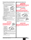
2. Turn the PRIME/SPRAY
valve to spray to bleed off
any pressure remaining in
the pump.
3. Remove the gun tip and
clean with a solution
appropriate to the type of
material being sprayed.
4. Remove the material
container and replace it
with a container of solvent
appropriate to the type of material being sprayed.
5. Check to be sure the pressure control knob is turned fully
counterclockwise to its lowest setting.
6. Turn the power switch to on.
7. Trigger the spray gun into a waste container until solvent
comes out and the pump, hose, and gun are clean.
8. Follow the pressure relief procedure found earlier in this
manual.
9. Make certain that the power switch is turned to off.
10. Turn the PRIME/SPRAY valve to spray to bleed off any
remaining solvent.
11. Unplug the unit and store in a clean, dry area.
Maintenance
Daily Maintenance
Perform the following procedures daily.
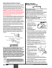
Filling the Packing Nut Reservoirs With Oil
Before you start to spray each day, squirt a
lubricant such as hydraulic oil into the slots in
the upper pump housing. Household oil and
cooking oil also work when hydraulic oil is not
available.
This lubricant keeps the piston seals pliant, minimizing paint
bypass and piston wear. If the unit is operated several hours a
day, lubricate approximately every 4 hours.
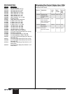
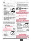
Cleaning the High Pressure Filter Screen
The high pressure filter will clog and
must be cleaned at least once a day.
1. Turn the filter body
counterclockwise to remove it
from the filter head.
2. Take out the filter sieve and
wash it thoroughly with the
appropriate solvent. Scrub the
filter sieve with a fiber-bristled
brush if necessary.
Do not use a wire brush. It could
damage the filter sieve.
NOTE: If you are using block fillers, mastics or other
similar materials, leave the filter out.
CAUTION
Filter Body
Filter Sieve
Filter Sieve
Support
O-Ring
Filter Head
NOTE: Do not apply so much that it
overflows and drips into the paint.
PRIME/SPRAY
Valve
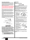
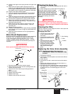
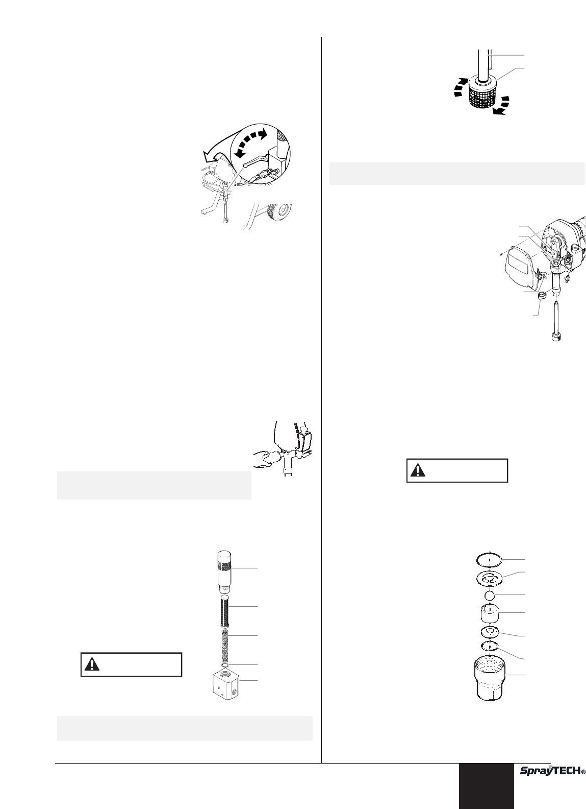
Cleaning the Intake Screen
1. Remove the intake
screen and clean with a
solvent appropriate to
the type of material
being used.
Repacking the Fluid Section
Repacking the fluid section includes replacing the packings as
well as any valve parts that show signs of wear.
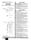
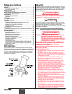
Removing the Fluid Section
1. Unscrew the siphon tube
assembly from the fluid
section assembly.
2. Unscrew the fluid hose from
the fluid section assembly.
3. Remove the return tube
clamp and move the return
tube away from the fluid
section assembly.
4. Unscrew the five screws
holding the front cover to the
pump housing and remove
the cover.
5. Unscrew the two screws
holding the packing nut cover
to the pump housing and remove the cover.
6. Carefully run the pump for short intervals until the
connecting pin is in front of the recessed area of the pump
housing.
7. Disconnect the pump’s power cord from the power supply.
8. Push the connecting pin out of the piston rod and yoke.
Use the short end of a hex wrench if necessary.
9. Loosen the locknut at the top of the fluid section assembly.
10. Unscrew the fluid section assembly from the pump.
Do not run the pump with the fluid section assembly
removed.
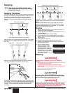
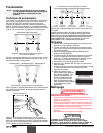
Disassembling the Fluid Section
Disassembling the Inlet Valve Housing
1. Place the wrench flats of the inlet valve housing into a
vise. Tighten the vise.
2. Unscrew the cylinder from the
inlet valve housing in a
counterclockwise direction.
Set the cylinder aside.
3. Remove and inspect the
upper o-ring. If damaged,
replace the o-ring during re-
assembly.
4. Remove the inlet valve
housing from the vise. Tap
out the lower ball stop disk,
the lower ball cage, and the
lower ball.
5. Remove the lower ball seat.
Inspect the ball and ball seat
for damage. If the lower ball
seat is worn or damaged it can be flipped to the unused
side during re-assembly. The lower ball must be replaced
if it is damaged or if the lower ball seat is flipped.
6. Remove the lower o-ring from the inlet valve holder.
Upper O-Ring
Lower Ball
Stop Disc
Lower Ball
Lower Ball
Cage
Lower Ball
Seat
Lower O-Ring
Inlet Valve
Housing
CAUTION
Pin
Yoke
Packing Nut
Cover
Return Tube
Clamp
NOTE: If any parts are difficult to disassemble, soak them
in an appropriate solvent until the paint softens.
Siphon Tube
Intake Screen
© SprayTECH Corporation. All rights reserved. 7