


35
GM 5000EAC.
B_03211
10
11
X
Y
1
14
12
12
Y
9
OPERATING MANUAL
EDITION 03/2012 PART NUMBER DOC 2319150
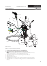
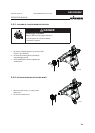
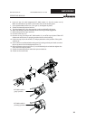
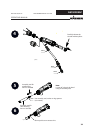
6. Insert air cap (10) with integrated ACF 5000 nozzle (11) into the union nut (9).
Make sure that the air cap horns (Y) lie in the recess of the nozzle guard.
7. Screw preassembled union nut (12) to gun (1) and tighten by hand.
8. Switch the material pressure back on.
9. Turn the trigger lock (14) to the spraying position and briefl y pull trigger.
10. When the blockage has been fl ushed out secure the gun with trigger lock.
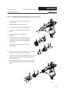
11. Relieve the pressure of gun and unit.
12. Unscrew union nut (12).
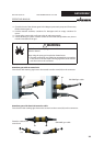
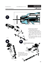
13. Remove air cap (10) and put ACF 5000 nozzle (11) out off air cap by hand. Clean ACF
5000 nozzle and insert it in spraying position into the valve housing.
14. Put the air cap (10) on the nozzle (11) and pay attention to the position of the guide
surfaces (X).
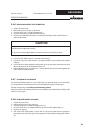
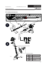
15. Screw union nut with attached nozzle guard (9) to the gun body and make sure that
the air cap horns lie in the designated recess (Y).
16. Before tightening the air cap horns (Y) set the desired jet level and then tighten the
union nut to the stop by hand.
17. Switch the material pressure and the air pressure back on.
18. Switch on the control unit.
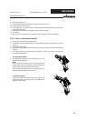
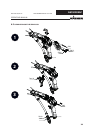
ACF 5000 nozzle in
„cleaning“ position
ACF 5000 nozzle in
„spray“ position