


43
GM 5000EAC.
3
B_03202
0.5 Nm
SW6
0.4 -
0.5 Nm
SW5
2
2
2
SW5/ 0.4 - 0.5 Nm
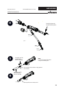
X = 123 ±0.1
SW2
1Nm
X
1
4
5
4
5
B_03203
SW9
1.2 Nm
OPERATING MANUAL
EDITION 03/2012 PART NUMBER DOC 2319150
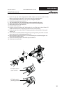
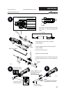
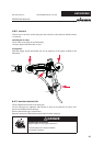
Insertion position compl. package
Set measure X with withdrawal nut and
then fasten it with the threaded pin
(SW2).
Note:
Use assembly tool, socket or
ring spanner (no wrench).
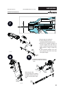
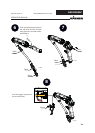
Ensure the correct
insertion position!
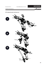
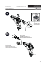
Ensure the correct
insertion position!
Push together the valve rod unit and the
compl. package.
Screw in together the valve rod unit and the
compl. package.
Remove the valve rod unit.
Tighten the compl. package.
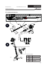
Carefully insert the valve rod unit and mount the
complete clamping screw (1) with assembly tool
(5).
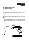
Tighten slightly AC valve
tip by hand using an
assembly tool
(Part No. 2309368).
Assembly tool
(Part No. 2325263).