12/01 AWB2700-1428GB
XC-NET-DP-M PROFIBUS-DP
module
13
The PROFIBUS-DP module can be fitted between the power supply
module and the CPU module.
Engineering
PROFIBUS-DP interface
Connect the module to the PROFIBUS-DP bus via the isolated
RS 485 interface (9-pole SUB-D socket/plug connector).
Power supply
The power supply module provides the 5 V supply to the modules
via the PC/104+ bus.
Start/Stop behaviour
Setting the OMS to the STOP position will cause all the outputs of
the remote devices to be set to 0.
An interruption on the DP line will cause all inputs of the discon-
nected devices (receive data) to be interpreted by the PLC as 0
signals and the outputs set by the PLC in the output module to be
reset.
Devices that are still connected with the PLC will continue to be
interrogated.
Configuring the module address
Up to three XC-NET-DP-M (PROFIBUS-DP) or XC-NET-CAN
(CANopen) modules can be used in any combination. Reserve a
memory range for each module in the CPU by defining a module
address for each one:
Setting the address on the device
X Set the address for each module using jumpers on the jumper
field in the jumper area 13 to 19 (a following figures).
Setting the address in XSoft
Assign the input/output address range (%IB/%QB) to the modules
in the PLC configuration in XSoft. The modules are integrated in
turn into the PLC configuration:
h
Use the special ZB4-209-DS2 PROFIBUS-DP plug. It
provides the wiring required for trouble-free operation up
to 12 Mbit/s.
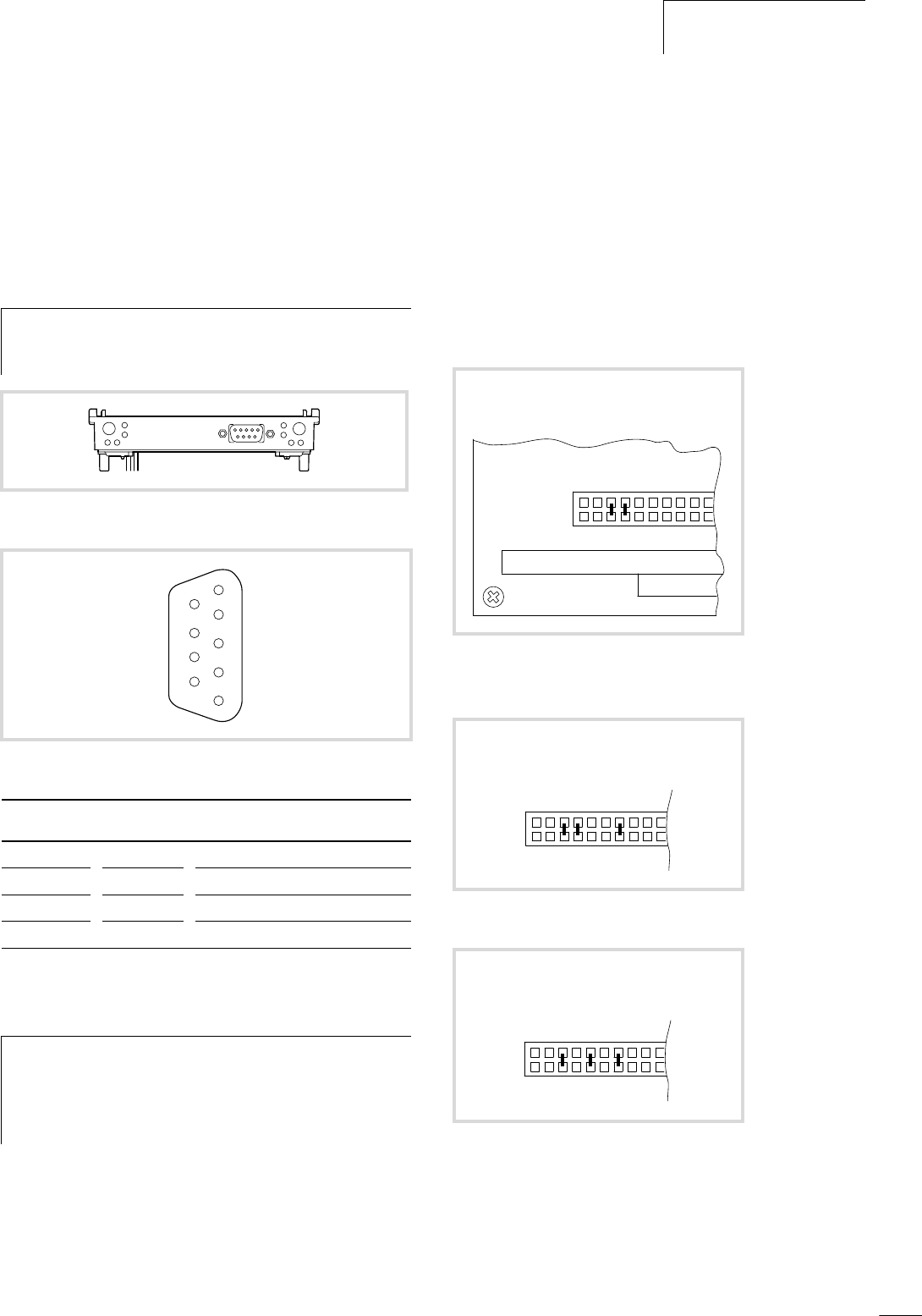
Figure 15: Connections of the PROFIBUS-DP module
Figure 16: Pin assignment of the PROFIBUS-DP interface
SUB-D plug Signal Meaning
3 RxD/TxD-P Receive/send data P
5 DGND Data reference potential
6 VP Supply voltage plus pole
8 RxD/TxD-N Receive/send data N
h
Set up the system power supply so that the connected
remote stations on the PROFIBUS-DP line are switched on
simultaneously or before the controller. This prevents any
errors occurring during the starting of the PROFIBUS-DP
line.
6
7
8
9
2
3
4
5
1
1. r CE000*
Figure 17: Address setting of module 1
* Factory setting
2. r CC000
Figure 18: Address setting of module 2
3. r D4000
Figure 19: Address setting of module 3
110
19 18 17 16 15 14 13
0111
110
19 18 17 16 15 14 13
0110
110
19 18 17 16 15 14 13
1010


