4 - Programming Examples
136
Generating Output Triggers
Providing that you have specified the appropriate trigger source, you can generate triggers as follows:
Single Triggers
u By sending one of the following over the GPIB:
TRIGger:IMMediate
*TRG
a group execute trigger
u By applying a signal with a high-to-low transition to the Trig In BNC connector.
u By pressing the front panel Trigger key when the unit is operating in local mode.
Continuous Triggers
u By sending the following commands over the GPIB:
TRIGger:SEQuence1:SOURce IMMediate
INITiate:CONTinuous:SEQuence1 ON
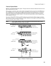
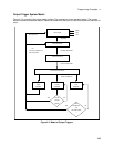
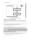
When the trigger system enters the Output Change state upon receipt of a trigger (see figure 4-2), the
triggered functions are set to their programmed trigger levels. When the triggered actions are completed,
the trigger system returns to the Idle state.
Specifying a Dwell Time for Each List Point
Each voltage and current list point has an associated dwell time specified by:
LIST:DWELl <n> {,<n>}
where <n> specifies the dwell time in seconds. The number of dwell points must equal the number of
output points. If a dwell list has only one value, that value will be applied to all points in the output list. After
each new output level or point is programmed, the output remains at that point in the list for the
programmed dwell interval before the list advances to the next point. Only an ABORt command can
transfer the system out of the Dwelling state.
At the end of the dwell interval, the transition to the next state depends on whether or not the list has
completed its sequencing and the state of the LIST:STEP command (see figure 4-2).
If the list is completed, the trigger system returns to the Idle state.
u If the list is not completed, then the system reacts as follows:
LIST:STEP ONCE programs the trigger system to return to the Initiated state to wait for the next
trigger.
LIST:STEP AUTO programs the trigger system to immediately execute the next list point.


