


BAD BOY™ SPOT LUMINAIRE USER MANUAL
8 02.9812.0001C
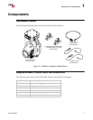
Major Components and Controls
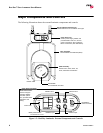
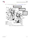
The following illustration shows the external luminaire components and controls.
Figure 1-2: Bad Boy Luminaire External Components and Controls
CONFIG
addr
043
univ A
1400w
ETHERNET
COMM
IN
DMX
THRU
15A Max
AC IN
200 -240 VAC
50 / 60 Hz
LAMP
hrs
125
temp 34C
INFO
01:34
TEST
COMM
DMX
STATUS
OK
ISPOWERED
ACTIVE ON LY
WHEN FIXTURE
200-240VA C
15A Max
50 / 60Hz
COMM
IN
DMX
THR U
ETHERNET
AC IN
ISPOWERED
ACTIVE ONLY
WHEN FIXTURE
Neutrik® AC
DMX512 Input
DMX512 Thru
Upper Enclosure Detail
Upper Enclosure -
Houses power supply, ballast, and
provides Data In and Thru, and AC
power connections. Also houses the
Menu Touchscreen (see detail below).
Hanging Bracket Assembly (2) -
Allows luminaire to be mounted on truss pipe.
Yoke Assembly -
Houses Master Control Board (MCB) .
FRONT VIEW
Power Connector
Front Lens -
8-inch diameter front lens.
Head Assembly -
Houses Color, Gobo, Zoom, Iris,
Frost, and Strobe mechanisms.
Ethernet Thru
Ethernet Input
Menu Touchscreen -
Used to configure
luminaire address
and other options.
Also, provides status
information and
testing.
Comm LED
Battery Wake Switch *
* Not available on all units