


#
T
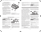
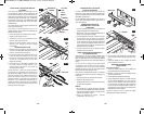
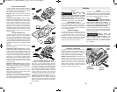
he planer comes with two chip exhaust ports,
which may be used with a chip bag (Fig.2) or a
shop vacuum and vacuum connector (Fig.3) to
keep your work environment cleaner. The chip
bag or vacuum connector may be attached to
either end of the exhaust port.
Moving the port selector lever to position 1
(towards front of tool) discharges chips to the
left, while position 2 (towards rear of tool)
discharges chips to the right. (Fig. 1)
The optional VAC002 adapter will connect the
hood to 1-1/4” and 1-1/2” vacuum hoses. An
adapter to connect the hood to 2-1/2" hoses is
also available separately.
• There are three types of blades that can be
used with the Bosch 1594 planer; standard
mini tungsten carbide blades, Bosch
Woodrazor micrograin mini tungsten carbide
blades (standard equipment with the Bosch
1594 planer), and large HSS blades.
• While the Bosch 1594 mini tungsten carbide
blades are sharper and more durable than
standard mini tungsten carbide blades, the
assembly and adjustment of both of
Woodrazor and standard tungsten carbide
blades are the same. Henceforth, all
references in this manual to “mini TC
blades” refer to both Woodrazor blades and
standard mini tungsten carbide blades.
• To use large HSS blades with the 1594 it is
necessary to purchase optional accessories.
"*&7 5749*(9.;* ,14;*8
<-*3 (-&3,.3, 51&3*7
'1&)*8),*8&7*8-&75&3)2&>(&:8*
.3/:7>
!
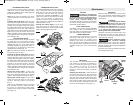
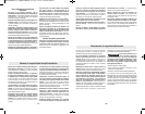
Mini TC planer blades have two cutting edges,
and may be reversed when one of the cutting
edges becomes dull or chipped. (Fig. 6)
Before any work on the machine itself, pull the
power plug.
Always changes both blades at the same time.
Otherwise, imbalance can cause vibration and
reduce the useful service life of the tool. Use
only blades designated for use with this model,
because other blades can cause vibration,
decrease performance and may not clamp
securely in blade holder. Do not attempt to
sharpen or use re-sharpened any TC blades.
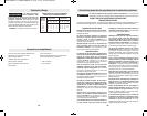
47*24;*9-*'1&)*8
1. Rotate the blade drum until the clamping jaw
is parallel to the planer shoe.
2. Loosen the three clamp screws by about
one revolution each. (It is not necessary to
remove the clamping jaw.) (Fig.4)
3. Slightly rotate the blade drum and use a
piece of wood to push the blade sideways
and out from under the clamping jaw. Make
sure to keep your fingers away from the
sharp edges of the blade. If the blade is
gummed and difficult to remove, you may
clean the blade and clamp with mineral
spirits, lacquer thinner or alcohol. (Fig. 5)
4. Rotate the blade drum 180° and repeat the
procedure to remove the second blade.
-8-
88*2'1>
FIG. 2
FIG. 3
CHIP BAG
EXHAUST
PORTS
VACUUM
CONNECTOR
(OPTIONAL)
!
WARNING
-7-
:3(9.43&1*8(7.59.43&3)5*(.+.(&9.438
.8(433*(99-*51:,+7429-*54<*784:7(*'*+47*2&0.3,&3>
&88*2'1>&)/:892*39847(-&3,.3,&((*8847.*8. Such preventive safety
measures reduce the risk of starting the tool accidentally.
!
WARNING
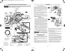
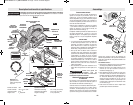
1&3*7
Model number 1594
Voltage rating 120 V 50 - 60Hz
Amperage rating 6.5 A
No load speed n
0
16,500/min
&=.2:2&5&(.9.*8
Planing depth 0 - 3/32" (0 - 2.6mm)
Rabbeting depth 0 - 5/16" (0 - 9mm)
Planing width 3-1/4" (82mm)
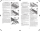
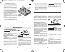
WING
KNOB
RABBETING
DEPTH STOP
(OPTIONAL)
DEPTH
ADJUSTMENT
KNOB
CHIP
EXHAUST
PORT
TRIGGER SWITCH
“LOCK-OFF”
BUTTON
PIVOT
FENCE
ROUND
KNOB
GUIDE
BRACKET
WING
KNOB
WING KNOB
FENCE
SCREW
DRIVE BELT COVER
CHAMFER
V-GROOVE
GUIDE
BRACKET
WIDTH
SCALE
WING
KNOB
FIG. 1
DEPTH
SCALE
Note: Each unlabeled
mark represents
0.5 mm.
BLADE WRENCH STORAGE
STANDARD
GUIDE
FENCE
DELUXE
GUIDE
FENCE
(OPTIONAL)
ADJUSTABLE
FRONT SHOE
PORT
SELECTOR
LEVER
PARK REST STAND
BM 2610028021 01-13_BM 2610028021 01-13.qxp 1/21/13 11:23 AM Page 7