


-12-
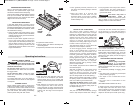
The cutting depth (planing depth) is
determined by the difference in height
between the adjustable front shoe and the
fixed rear shoe of the planer. The depth knob
adjusts the front shoe, which retracts and
exposes the blade and determines the
amount of material removed from the
workpiece. The cutting depth range is from 0
to 3/32” or 2.6 mm per pass. (Fig. 1)
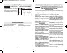
The appropriate depth of cut and feed rate
depends on the workpiece material:
To avoid clogging and/or damage to the
motor, a more shallow (thin) cut and/or a
slower feed rate may be needed if the
material has any of these characteristics:
hardness; gumminess, sappiness, moisture,
paint, varnish and/or knots. Also, when
planing against the grain or across the grain
rather than with the grain, a shallower cut
and/or slower feed rate is required.
Whenever possible, test by planing a similar
piece of scrap material.
Use multiple, progressive cuts to achieve the
total desired depth.
Start with a shallow cut. If the plane moves
freely through the workpiece with no
excessive load on the motor, the depth
setting can be increased before the next cut.
(Do not change depth of cut while planing.)
When near the desired total depth, re-adjust
the planing depth to a shallow setting for the
final cut to obtain a good surface finish.
)/:89.3,9-**59-4+:9 Rotate depth
adjustment knob clockwise until the indicator
is aligned with the desired cutting depth on
the depth scale (Fig. 1).
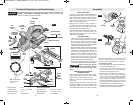
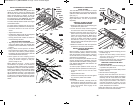
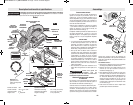
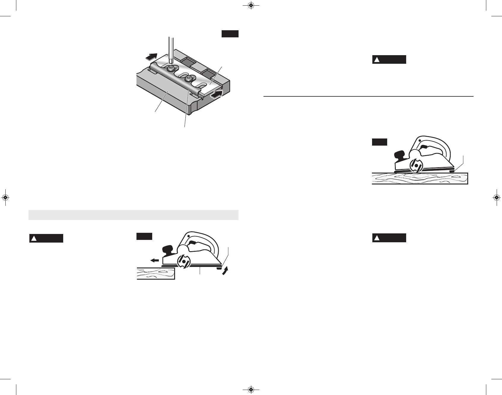
The park rest stand automatically springs
down to help keep the blade from coming in
contact with the work surface when planer is
not in use (Fig. 11). The park rest stand is
designed to swing up and out of the way by it
itself when the back of the plane crosses the
leading edge of the workpiece (Fig. 10). It will
also swing up when planing begins in the
middle of the work piece (in from the edge of
the work piece).
#
$
*24;*51:,+74254<*7
84:7(* .+ .9 '*(42*8
3*(*88&7>942&3:&11>7*24;*(-.58 The
blades are hidden from view and you may be
cut if contacted.
To minimize the possibility of clogging, make
sure:
1. Chip eject lever is all the way forward (left
eject) or back (right eject).
2. The depth of cut is reasonable for the
material.
3. The feed rate is reasonable for the
material.
(See FEED RATE & DEPTH OF CUT)
If clogging occurs, stop the planer and move
the chip eject lever back and forth. If this
does not break up the clog, unplug the planer
and carefully insert a screwdriver or similar
object into the dust port to break up the clog.
3. Then gradually transfer pressure to the
rear shoe, and continue planing to the end
of the cut.
4. Feed the planer at a uniform and
reasonable rate that does not put
excessive strain on the motor or blades,
(do not pull the planer back over the
surface already cut.)
5. Use progressive cuts until you are near the
desired depth, and then re-adjust to a
shallow cut for the final pass to obtain a
good surface finish.
-* 24947 2&> 89&11 .+
.25745*71> :8*) 47
4;*714&)*) Reduce the pressure (feed
rate) or depth of cut to prevent possible
damage to the tool if the motor labors.
!
CAUTION
FIG. 11
PARK
REST
!
WARNING
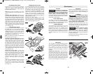
Worn or dull HSS plane blades can be re-
sharpened. The optimal blade angle of 50°
should be maintained when sharpening.
O
nce a total of 6 mm of steel has been removed
from tips of the blades, both blades must be
replaced because the minimum HSS blade
height is 23 mm from back to tip.
!
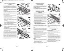
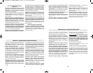
A PA1206 HSS Blade Leveling Fixture
(optional accessory) is required to level new or
resharpened HSS blades. (Not necessary with
the PA1204 HSS Blades and Retainers, which
are leveled at the factory.)
1. Place the blade and blade retainer on the
leveling fixture and make sure that the blade
retainer engages in the grooves intended for
this purpose. (Fig. 9)
2. Press the plane blade against the stop in
front of the cutting edge to achieve the
proper depth and evenness (levelness) and
with the blade retainer in this position and
tighten it with the locking screws. This will
automatically adjust the blade to the correct
height and levelness.
3. Tighten the retainer screws.
4. Remove blade and retainer assembly from
the leveling fixture.
5. Repeat the procedure for the second blade.
-11-
FIG. 9
HSS
BLADE
BLADE
RETAINER
BLADE
LEVELING
FIXTURE
5*7&9.3,3897:(9.438
"
41)9-*9441<.9-'49-
-&3)8<-.1*89&79.3,9-*
94418.3(*9476:*+7429-*24947(&3
(&:8*9-*9441949<.89
49:739441 depress the “Lock-Off”
release button from either side and squeeze
the trigger switch.
49:739-*9441 release the trigger
switch and it will return to "OFF" position
automatically.
To increase switch life, do not turn switch on
and off while tool and drum are held against
a workpiece.
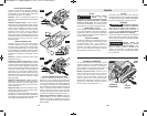
Proper planing action helps to achieve the
desired result. With practice and experience,
it will become second nature. Make sure that
the workpiece is held in place securely on
your work surface, and standing comfortably,
hold the planer firmly with both hands.
1. With the planer fully adjusted, place the
front shoe on the workpiece, (be certain
that the blade drum is not in contact with
the work) and start the planer as described
earlier.
2. With pressure on the front shoe, and the
fence against the side of the work (to
control the width or angle,) feed the planer
steadily until the full length of the rear shoe
passes over the edge of the workpiece.
(Fig. 10)
!
WARNING
FIG. 10
BM 2610028021 01-13_BM 2610028021 01-13.qxp 1/21/13 11:23 AM Page 11