


*7;.(*
7*;*39.;*2&.39*3&3(*
5*7+472*)'>:3&:9-47.?*)
5*78433*12&>7*8:19.32.851&(.3,4+
.39*73&1<.7*8&3)(42543*398<-.(-
(4:1) (&:8* 8*7.4:8 -&?&7) We
recommend that all tool service be performed
by a Bosch Factory Service Center or Autho -
rized Bosch Service Station.
Your Bosch tool has been properly lubricated
and is ready to use. It is recommended that
tools with gears be regreased with a special
gear lubricant at every brush change.
The brushes and commutator in your tool
have been engineered for many hours of
dependable service. To maintain peak
efficiency of the motor, we recommend every
two to six months the brush es be examined.
Only genuine Bosch replace ment brushes
specially designed for your tool should be
used.
Bearings which become noisy (due to heavy
load or very abrasive material cut ting) should
be replaced at once to avoid overheating or
motor failure.
1*&3.3,
4&;4.)&((.)*398&1<&>8
).8(433*(99-*9441+742
9-*54<*78:551>'*+47*(1*&3.3,47
5*7+472.3,&3>2&.39*3&3(* The tool may
be cleaned most effectively with compressed
dry air. 1<&>8<*&78&+*9>,4,,1*8<-*3
(1*&3.3,94418<.9-(4257*88*)&.7
Ventilation openings and switch levers must
be kept clean and free of foreign matter. Do
not at tempt to clean by inserting pointed
objects through openings.
*79&.3(1*&3.3,&,*398
&3) 841;*398 )&2&,*
51&89.(5&798 Some of these are: gasoline,
carbon tetrachlo ride, chlo rinated cleaning
solvents, ammonia and house hold detergents
that contain ammonia.
Clean the park rest shoe regularly and ensure
that it springs back freely.
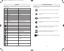
!
WARNING
!
WARNING
!
CAUTION
!
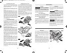
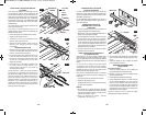
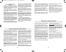
The drive belt is a normal maintenance part
and should be inspected periodically for
wear. If the drive belt shows signs of drying
out, cracking or tearing, it should be
replaced. If the drive belt will not track
properly or comes off the pulleys, it should be
replaced.
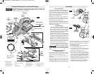
389&11.3,3*<)7.;*'*19 Loosen screw and
remove the drive belt cover. Cut and remove
the worn drive belt. Before installing the new
drive belt, clean both pulleys thoroughly. First
place the new drive belt onto the drive pulley
then rotate clockwise while pushing the belt
onto the driven pulley. Reinstall the drive belt
cover and securely tighten screw (Fig. 15).
-14-
FIG. 15
DRIVE
PULLEY
DRIVEN
PULLEY
DRIVE
BELT
DRIVE BELT
COVER
SCREW
&.39*3&3(*
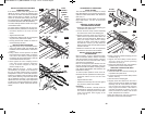
The guide fence can be used to control the
width of the cut or for simply providing added
stability and protection when cutting materials
that are up to 3-1/4" wide.
49* When used for rabbeting, the fence
must be attached to the left side of the tool.
(Fig. 1).
389&11.3,9-*,:.)*+*3(* Place the wing
knob through the appropriate hole in the guide
bracket and screw into preferred side of the
housing. Securely tighten wing knob. Setting
the cutting width: Place wing knob through the
appropriate fence arm and slide along the
guide bracket to the desired position. Securely
tighten wing knob. Be certain that the flat
washer (supplied) is fitted between the bottom
of the guide fence and wing knob or the guide
fence is likely to slip.
#
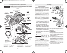
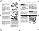
The deluxe guide fence can be used to control
the width of the cut or for simply providing
added stability and protection when cutting
materials that are up to 3-1/4" wide, with the
additional capability of guiding the planer on
any angle up to 45 degrees, to allow edge
chamfering and beveling (Fig. 12).
49* The deluxe fence must be attached to
the left side of the tool. (Fig. 1).
389&11.3,9-*)*1:=*,:.)*+*3(* Place the
wing knob through the appropriate hole in the
guide bracket and screw into left side of the
housing. Securely tighten wing knob. Setting
the cutting width: Place wing knob through the
left fence arm and slide along the guide
bracket to the desired position. Securely
tighten wing knob. Be certain that the flat
washer (supplied) is fitted between the bottom
of the guide fence and wing knob or the guide
fence is likely to slip.
*99.3,9-*(:99.3,<.)9- Loosen wing
knob and using the width scale, slide the
fence along the guide bracket to the desired
position. Securely tighten wing knob (Fig. 1).
*99.3,9-*(:99.3,&3,1* Loosen round
knobs and pivot the fence to the desired
position. Securely tighten round knobs
(Fig. 1).
Note that the adjustable front shoe contains
three chamfer V-grooves, which will follow
the corner of a workpiece to allow easier
handling when using the deluxe angle/width
fence (Fig. 13).
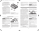
The optional rabbeting depth stop accessory
(Fig. 1) allows the user to set any rabbeting
depth from 0 to 5/16 inch. For best results, it
is important that the blade be properly
aligned (See "BLADE ALIGNMENT"). The
width of the rabbet is controlled by the width
fence. The final depth is achieved by
repetitive cutting until the rabbeting depth
guide contacts the workpiece. The maximum
rabbeting depth is 5/16"
*99.3,9-*7&''*9)*59- Loosen wing
knob and using the depth scale on the
rabbeting depth stop, set the desired rabbet
depth. Securely tighten wing knob.
-13-
82
m
m
m
ax
9 mm
m
ax
45°
FIG. 12
FIG. 13
82 m
m
m
ax
9 mm
max
FIG. 14
BM 2610028021 01-13_BM 2610028021 01-13.qxp 1/21/13 11:23 AM Page 13