


17B@A6;43?<;A@A./696G6;43<<A
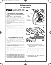
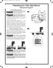
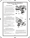
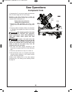
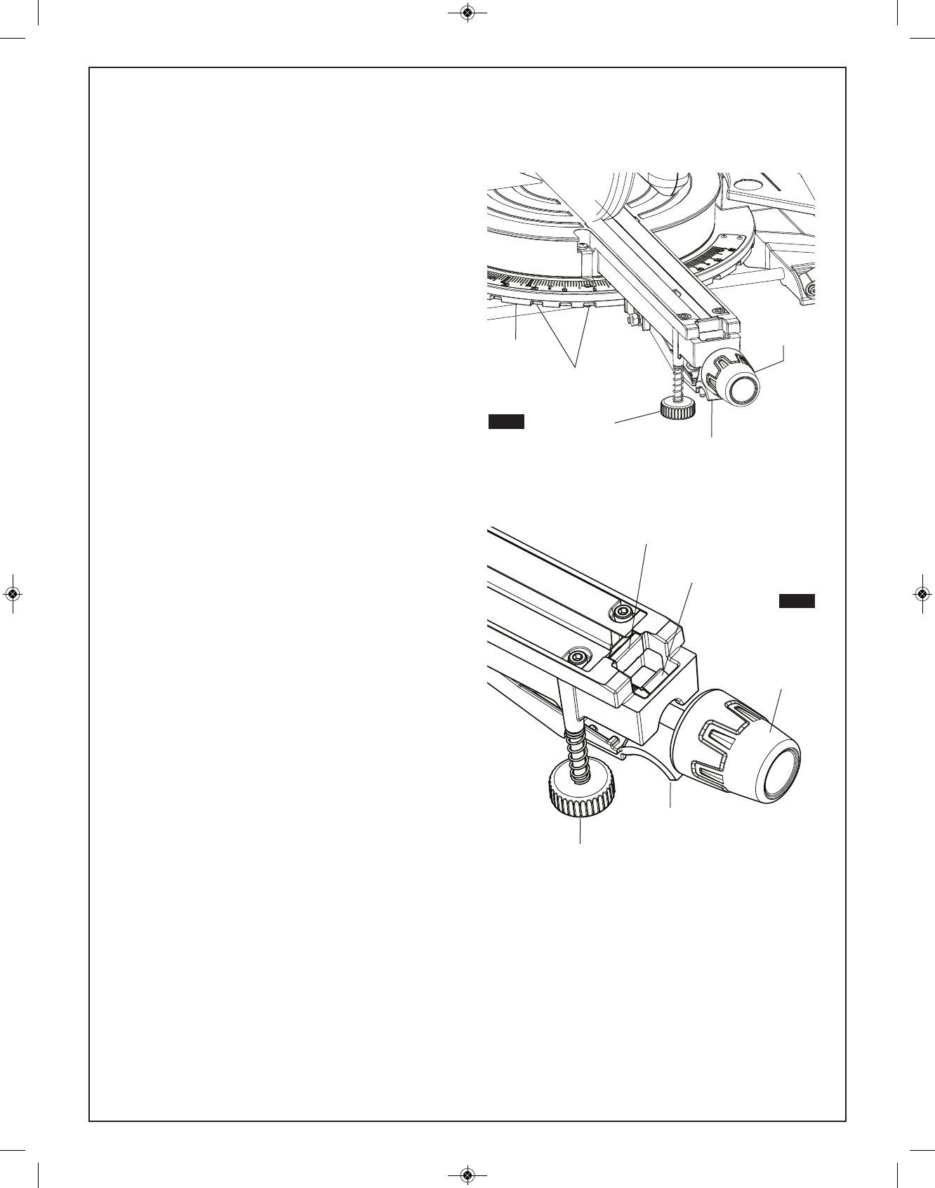
The front stabilizing foot is located at the front of the
saws table near the detent override (figure 36) this foot
provides additional support and stability when making
slide cuts. To adjust the foot to the work surface follow
these steps:
1. Place the saw on the intended work surface.
2. Set desired miter angle.
3. Unscrew (turn counter clockwise) the front stabilizing
foot until it contacts the work surface.
4. Screw in (turn clockwise) the front stabilizing foot if it
prevents the tool from making full contact (all four
base feet touching) with the work surface.
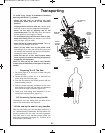
Note: if the saw is firmly attached to a bench using all
mounting holes the front stabilizing foot can be adjusted
clockwise into the saw and does not need to be adjusted
to the work surface (refer to Page 22, How to mount the
saw to a bench).
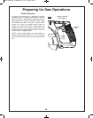
$?2=.?6;43<?&.D#=2?.A6<;@
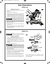
!6A2?2A2;A
(@6;4A52!6A2?2A2;A
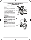
1. Loosen the miter lock knob about 1/2 turn (see figure
35).
2. Grip the lock knob, and then reach down with your
index finger to pull up on the miter detent lever – pull
lever until it is out from the miter detent plate.
3. While gripping the miter lock knob and miter detent
lever, rotate the saw’s table. Stop table rotation at the
d
esired angle as indicated by the miter scale pointer.
4. Release the miter detent lever into a detent in the
miter detent plate or at an angle between detents. If
close to a miter detent, use the miter detent override
feature.
5. Tighten the miter lock knob before cutting.
NOTE: It is recommended to tighten the miter lock knob
before all cuts. It is required to tighten the knob before
cutting at any angle between detents or when the miter
detent override system is in use.
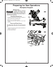
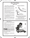
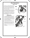
!6A2?2A2;A#C2??612
The miter detent override feature allows the miter detent
action to be locked out, allowing for micro adjustments
at any miter angle. When the desired miter angle is too
close to a standard mitering angle that has a detent slot,
this feature prevents the wedge on the miter detent
lever from slipping into the detent slot on the miter
detent plate.
1. Lift and hold the miter detent lever.
2. Push the detent override clip forward and latch in
place over clip edge. Release miter detent lever
(figure 36).
3. Rotate table to any position on the miter scale.
4. Lock the miter lock knob to retain miter position.
'<6@2;4.42
Loosen miter lock knob and lift the miter detent lever to
release the detent override clip. The clip should
automatically disengage and the table should lock into
any desired miter detent.
!6A2?
2A2;A 2C2?
!6A2?
<08;</
2A2;A@
2A2;A
$9.A2
2A2;A
#C2??61296=
96=142
!6A2?
2A2;A 2C2?
!6A2?
<08;</
FIG. 35
FIG. 36
?<;A
&A./696G6;4
<<A
?<;A
&A./696G6;4
<<A
BM 2610025580 05-13_BM CM8S 5/17/13 1:37 PM Page 28