


37
Garantía Limitada 5-3-1
1.Duración: El fabricante garantiza que reparará, sin costo alguno por repuestos o mano de obra la soldadora o la pistola o los cables que
estén dañados bien en material o mano de obra, durante los siguientes periodos después de la compra original:
Por 5 años: El transformador y rectificador de la soldadora
Por 3 años: Toda la soldadora (se excluyen: pinzas, pistola,portaelectrodos, cables, o accesorios que vienen con la soldadora)
Por 1 año: Pinzas, Pistola, Portaelectrodo, Acessorios y Cable para Soldar (de haberlos)
2. QUIEN OTORGA ESTA GARANTIA (EL GARANTE):
Campbell Hausfeld
The Scott Fetzer Company
100 Production Drive
Harrison, OH 45030
Teléfono: (513)-367-4811
3. BENEFICIARIO DE ESTA GARANTIA (EL COMPRADOR): El comprador original del producto Campbell Hausfeld.
4. Cobertura de la garantía: Defectos en material y fabricación que ocurran dentro del periodo de validez de la garantía. La garantía
cubre la soldadora, el transformador y rectificador, la pistola o el portaelectrodo y los cables sólamente.
5. Lo que no está cubierto por esta garantía:
A. Las garantías implicitas, incluyendo las garantías de comercialidad y conveniencia para un fin particular SON LIMITADAS A LA DURACION
EXPRESA DE ESTA GARANTIA. Después de este periodo, todos los riegos de pérdida, por cualquier razón, serán la responsabilidad del
propietario del producto. En algunos estados no se permiten limitaciones a la duración de las garantías implicitas, por lo tanto, en tal caso
esta limitación o exclusión no es aplicable.
B. CUALQUIER PERDIDA, DAÑO INCIDENTAL, INDIRECTO O CONSECUENTE O GASTO QUE PUEDA PUEDA RESULTAR DE UN DEFECTO, FALLA
O MAL FUNCIONAMIENTO DEL PRODUCTO CAMPBELL HAUSFELD. En algunos estados no se permite la exclusión o limitación de daños
incidentales o consecuentes, por lo tanto, en tal caso esta limitación o exclusión no es aplicable.
C. Esta garantía no cubre aquellos accesorios que se desgastarán con el uso normal del producto; la reparación o reemplazo de los mismos
será la responsabilidad del propietario. Ejemplos de los productos de desgaste por el uso son (lista parcial): Bqouillas de contacto, boquillas,
forros internos de la pistola, bobinas, felpa para limpiar el alambre. Además, esta garantía no cubre daños que ocurran al reemplazar o darle
servicio a las piezas arriba enumeradas.
D. Cualquier falla que resulte de un accidente, abuso, negligencia o incumplimiento de las instrucciones de funcionamiento y uso indicadas
en el(los) manual(es) que se adjuntan al producto.
E. Servicio antes de entrega, por ejemplo ensamblaje y ajustes.
7. Responsibilidades del Garante bajo esta Garantía: Reparar o reemplazar, como lo decida el garante, los productos o componentes
defectuosos durante el periodo de validez de la garantía.
8. Responsibilidades del Comprador bajo esta Garantía:
A. Entregar o enviar el producto o componente a Campbell Hausfeld. Los gastos de flete, si los hubiere, deben ser pagados por el comprador.
B. Ser cuidadoso con el funcionamiento del producto, como se indica en el(los) manual(es) del propietario.
9. Cuando efectuará el garante la reparación o reemplazo cubierto bajo esta garantía: La reparación o reemplazo dependerá del
flujo normal de trabajo del centro de servicio y de la disponibilidad de repuestos.
Esta garantía limitada le otorga derechos legales especificos y usted también puede tener derechos que varian de un estado a otro.
~
~
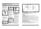
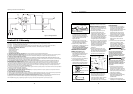
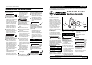
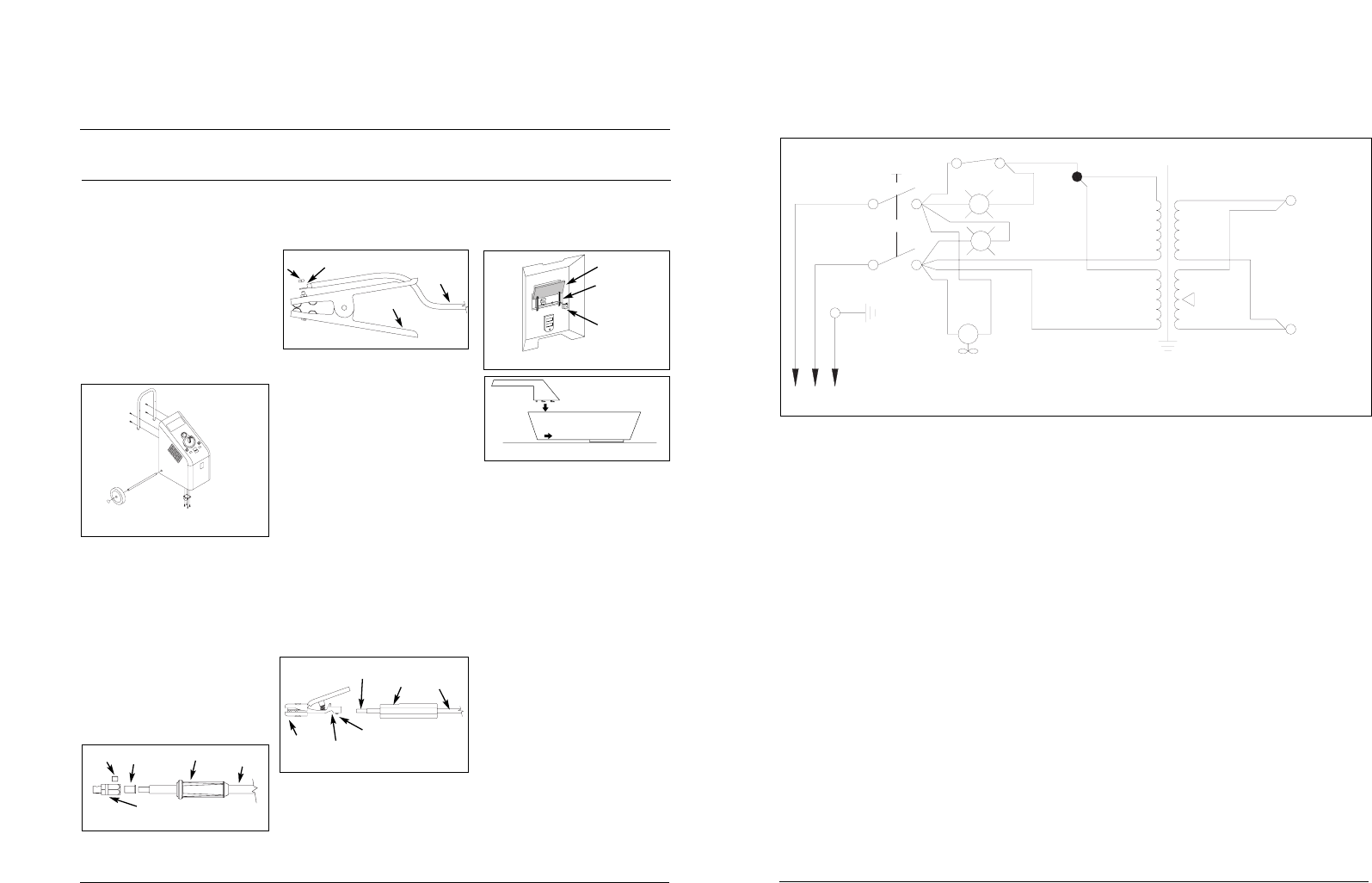
Encendido/Apagado
Tierra
Negro
Blanco
Verde
S2
NC
T1
S2
M
G
Y
S1
Figura 15 - Esquema del cableado
clamp.
2. Slide welding cable with ring
connector through hole in work clamp.
3. Attach ring connector to work clamp
with hex nut removed in step 1.
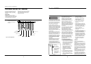
ELECTRODE HOLDER ASSEMBLY
(See Figure 5)
1. Loosen the handle setscrew in the
electrode holder a few turns. Do not
remove this setscrew completely.
Remove the insulated handle and slide
it over the end of the welding cable
with the crimped sleeve.
2. Loosen the cable setscrew in the
bottom of the brass body of the
electrode holder.
3. Slide the welding cable/crimped
sleeve into the back of the brass body,
aligning the flat side of the crimped
connector with the face of the cable
setscrew.
4. Tighten the cable setscrew to
securely hold the welding
cable/crimped sleeve.
5. Slide the insulated handle onto the
electrode holder and tighten the
handle setscrew. Do not overtighten
this setscrew. Overtightening will
damage the insulated handle.
HAND SHIELD ASSEMBLY (See
Figures 6 & 7)
1. Cut retainer stiffeners and
detachable handle away from shield.
Trim the excess plastic to remove sharp
edges.
2. Insert the filter lens.
4
Operating Instructions and Parts Manual
Shielded Metal Arc Welder
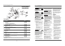
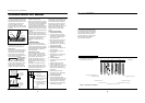
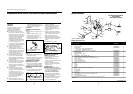
HANDLE ASSEMBLY (See Figure 2)
1. Fasten end caps onto handle.
2. Handle may be attached in two
positions (high or low). Using the four
screws and washers provided, attach
the handle to the back of the case
WHEEL ASSEMBLY (See Figure 2)
1. Slide the axle through the holes in
the sides of the case.
2. Slide the wheels onto the axle and
lightly tap the pal-nuts into place on
the axle grooves.
CASTER ASSEMBLY (See Figure 2)
1. Using the eight screws and washers
provided, attach the casters to the
bottom of the case.
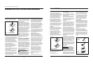
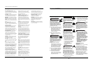
DINSE PLUG ASSEMBLY (See Figure
3)
1. Strip 1/2” of insulation from the end
of the welding cable opposite the
crimped connectors.
2. Insert this end of the welding cable
through the dinse plug boot and slide
the bare wire into the copper sleeve.
3. Insert the welding cable/copper
sleeve assembly into the back of the
dinse plug.
4. Tighten the setscrew, securing the
cable in place.
5. Slide the boot over the hex portion
of the dinse plug.
6. Repeat for the other lead.
WORK CLAMP ASSEMBLY (See
Figure 4)
1. Remove one hex nut from work
3. Attach the stiffeners over the pins on
the lens retainers.
4. To attach the handle, place shield on
a flat surface and press handle into
place.
www.chpower.com
MODEL WT1000 (See Figure 8)
1. Remove the lens retainer from the
face shield with a regular screwdriver
by prying against the shield and post
of the lens retainer.
2. Remove the protective film covering
from both sides of each lens cover.
Put one clear lens cover on each side
of the shaded lens. Place these three
lenses together into the face shield
and secure with the lens retainer. The
lens retainer should snap into the
second notch in the face shield.
3. Position one of the holes in the
adjustment arm over the pins which
are located in the ear area of the face
shield. These adjustment arms control
the closeness of fit and can be easily
repositioned if necessary.
4. Position the headgear inside the face
shield. Assemble the helmet by
inserting the stud screw through the
headgear and shield into the tension
nut as shown. Do not tighten tension
nut completely.
5. Trial fit the welding helmet. Adjust
headgear ratchet band to a
comfortable position and lower the
WELDING HELMET ASSEMBLY
(Promotional Models Only)
Welding
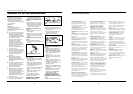
Cable
Ring Connector
Work
Clamp
Hex
Nut
Figure 2 – Handle, Wheel and Caster
Assembly
Figure 3 - Dinse Plug Assembly
Set Screw
Boot
Welding
Cable
Wire
Sleeve
Dinse Plug
Electrode
Holder
Handle
Setscrew
Cable
Setscrew
Crimped
Sleeve
Handle
Welding
Cable
Figure 4 – Work Clamp Assembly
Figure 5 – Electrode Holder
Lens
Lens
Retainer
Retainer
Stiffener
Figure 6 – Hand Shield
Figure 7 – Hand Shield