


36
Manual de instrucciones y lista de repuestos
DIAGNOSTICO DE AVERIAS
Problema Posibles Causas Acción a tomar
La soldadora no hace ruido al
encenderla (La luz verde no está åΩ
La soldadora hace ruido pero no
suelda
La soldadora le da corrientasos
La soldadora se sobrecalienta - se
queman los fusibles o el
cortacircuito se activa
Se le dificulta encender el arco
Reborde es muy delgado en
algunos sitios
Reborde es muy grueso en algunos
sitios
Los bordes de la soldadura están
disparejos
El reborde no penetra el metal
básico
El electrodo se pega a la pieza de
trabajo
El electrodo salpica y se pega
1. No hay corriente en el
tomacorrientes
2. El cordón eléctrico está
roto o dañado
1. La electricidad en el
electrodo no es la
adecuada
2. Hay conexiones mal
hechas en la soldadora
1. Contacto accidental con
la pieza de trabajo
2. Hay transmisión de
corriente debido a la
humedad en la ropa o el
área de trabajo
1. Uso de un cordón de
extensión
2. El diámetro del elec-
trodo es muy grande
3. El circuito está sobre-
cargado
1. El diámetro del
electrodo es muy grande
2. La pieza de trabajo no
está conectada a tierra
adecuadamente.
3. El voltaje se ha reducido
debido a carga excesiva
1. La velocidad de
desplazamiento varia
2. El nivel del amperaje es
muy bajo
1. La velocidad de
desplazamiento varia o
es muy lenta
2. El nivel del amperaje es
muy alto
1. La velocidad de
desplazamiento es muy
rápida
2. El arco es muy corto
3. El nivel del amperaje es
muy alto
1. ILa velocidad de
desplazamiento varia
2. l nivel del amperaje es
muy bajo
El electrodo está en
contacto con la pieza de
trabajo cuando el arco está
encendido
Los electrodos están
húmedos
1. Chequée el fusible o el cortacircuito
2. Debe darle servicio
1. Chequee la pinza de conexión a tierra, el cable y la conexión a la
pieza. Chequee el cable del electrodo y la pinza.
2. Chequee todas las conexiones externas de la soldadora
1. Evite hacer contacto con la pieza de trabajo
2. Cerciórese de que la ropa y el área de trabajo estén secas
1. Si es posible, reubique la soldadora para evitar el uso de cordones de
extensión. Si no la puede reubicar, use un cordón de extensión más
grueso (de un número más bajo)
2. Use un electrodo de un diámetro más pequeño
3. La soldadora requiere una línea exclusiva
1. Use un electrodo de un diámetro más pequeño
2. Cerciórese de que la conexión a tierra es adecuada ( no hay pintura,
barniz u óxido)
3. Conecte la soldadora a una línea exclusiva
1. Disminuya y mantenga la velocidad de desplazamiento
2. Debe aumentarlo o usar un electrodo de un diámetro más pequeño
1. Debe aumentarla y mantenerla constante
2. Debe bajarlo
1. Debe reducirla
2. Debe aumentarlo
3. Debe bajarlo
1. Debe reducirla y mantenerla constante
2. Debe aumentarlo
Mantenga el electrodo a la distancia adecuada tan pronto haya
encendido el arco
Use electrodos secos y siempre almacene los electrodos en un sitio seco
Para mayor información sobre este producto llame al
1-800-746-5641 (desde los E.E.U.U.)
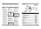
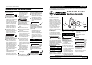
4. Connect the ground clamp to the
work piece or workbench (if metal).
Make sure the contact is secure, and
not obstructed by paint, varnish,
corrosion, or non-metallic materials.
5. Insert the exposed part of the
electrode (the end with no flux) into
the jaws of the electrode holder.
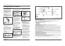
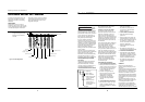
6. Set the amperage adjustment knob
to the proper amperage for the
electrode diameter. Refer to the
following chart for proper electrode
current settings.
The electrode
holder and rod are
electrically "hot"(have current
potential) when the welder is on.
Grounding against any metallic surface
may produce an arc which could cause
sparks and damage eyesight.
7. Hold the electrode and holder away
from the grounded work piece or
workbench. Turn on the welder. A
green light is illuminated when the
welder power is on.
8. Position the electrode to begin weld,
lower the welding helmet or
position the hand shield, and strike
an arc. Adjust weld amperage as
needed.
9. When finished welding, turn welder
off and store properly.
Duty Cycle / Thermostatic
Protection
Welder duty cycle is the percentage of
actual weld time that can occur in a ten
minute interval. For example, at a 10%
duty cycle, actual welding can occur for
one minute, then the welder must cool
for nine minutes.
Internal components of this welder are
protected from overheating with an
automatic thermal switch. A yellow
lamp is illuminated on the control panel
!
WARNING
Model WS2800
5
Operation
1. Be sure to read, understand, and
comply with all precautions in the
General Safety Information section.
Be sure to read the entire section
entitled Welding Guidelines prior to
using this equipment.
2. Turn welder off and plug into
appropriate receptacle: 230v-50 amp
3. Verify that the surfaces of metals to
be joined are free from dirt, rust,
paint, oil, scale or other
contaminants. These contaminants
make welding difficult and cause
poor welds.
All persons
operating this
equipment or in the area while
equipment is in use must wear
protective welding gear including: eye
protection with proper shade, flame
resistant clothing, leather welding
gloves, and full foot protection.
If heating,
welding, or cutting
materials that are galvanized, zinc
plated, lead, or cadmium plated refer
to the General Safety Information
Section for instructions. Extremely
toxic fumes are created when these
metals are heated.
!
WARNING
!
WARNING
if the duty cycle is exceeded. Welding
operations may continue when the
yellow lamp is no longer illuminated.
Maintenance
Disconnect power
supply and turn
machine off before inspecting or
servicing any components.
Before every use:
1. Check condition of weld cables and
immediately repair or replace any
cables with damaged insulation.
2. Check condition of power cord and
immediately repair or replace any
cord if damaged.
3. Check condition of electrode holder
insulating pieces and immediately
replace cracked or missing insulators.
Verify that all fasteners are tight and
insulated.
Do not operate this
welding machine
with cracked or missing insulation on
welding cables, electrode holder, or
power cord.
Every 3 months:
Replace any unreadable labels on the
welder. Use compressed air to blow all
dust and lint from the ventilation
openings.
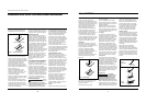
Welding Guidelines
General
This line of welding machines utilizes a
process known as Shielded Metal-Arc
Welding (SMAW). This process is used
to bond metals by heating them with
an electric arc created between the
electrode and the work piece.
Electrodes used for shielded metal arc
welding have two parts. The inner core
is a metal rod or wire that should be
similar in composition to the base
metal. The outer coating is called flux.
Various types of flux exist. Each coating
is used for a particular welding
situation.
While the metal is molten, it can be
contaminated by elements in the air.
This contamination could weaken the
weld. The flux coating creates a
protective barrier called slag that
protects the molten metal from
contaminants.
!
WARNING
!
WARNING
www.chpower.com
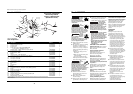
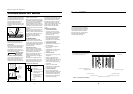
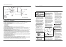
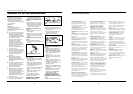
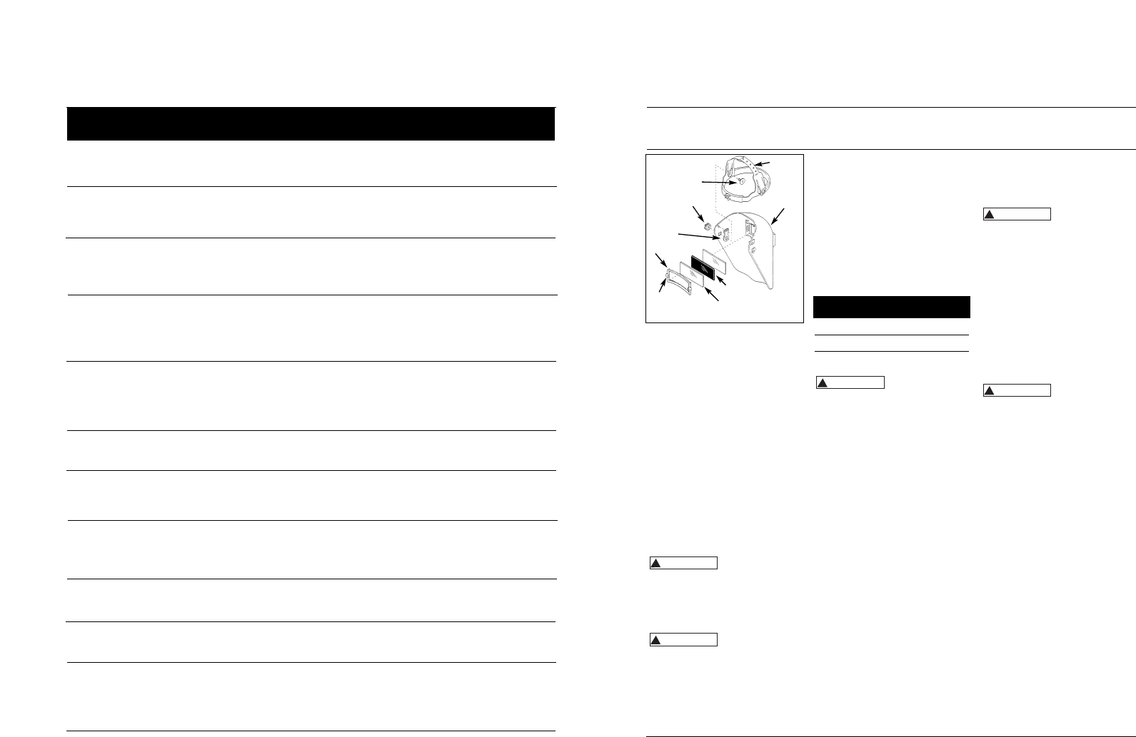
Figure 8 – Helmet Assembly
Headgear
Face Shield
Shaded Lens
Clear Lens Cover (2)
Post
Lens Retainer
Adjustment
Arm (2)
Tension Nut (2)
Stud Screw (2)
face shield. If the shield is too far or
too close to the face, use a different
hole in the adjustment arm. Adjust the
tension nuts so that helmet can be
easily lowered over the face by
nodding the head.
Electrode Current
Diameter Setting (Amps)
3/32" (2.5 mm) 60-110
1/8" (3.2 mm) 110-160
5/32" (4.0 mm) 150-230