


Step 10—Start-Up
To prevent compressor damage or personal injury, observe
the following:
• Do not overcharge system with refrigerant.
• Do not operate unit in a vacuum or at negative pressure.
• Do not disable low-pressure switch.
To prevent personal injury wear safety glasses, protective
clothing, and gloves when handling refrigerant and observe
the following:
• Back seating service valves are not equipped with Schrader
valves. Fully back seat (counterclockwise) valve stem before
removing gage port cap.
Do not vent refrigerant to atmosphere. Recover during system
repair or final unit disposal.
Follow these steps to properly start up the system:
1. The outdoor unit is equipped with a crankcase heater which
operates when the compressor is off. Energize crankcase
heater 24 hr before starting unit. To energize heater only, set
indoor thermostat to OFF position and close power disconnect
to unit.
NOTE: Starting the compressor without a minimum of 12 hr of
crankcase heat prior to initial start-up, may result in a compressor
chattering noise and possible damage to the compressor.
2. Fully back seat (open) liquid and vapor tube service valves.
3. Unit is shipped with valve stem(s) front seated and caps
installed. Replace stem caps after system is opened to refrig-
erant flow (back seated). Replace caps finger tight and tighten
additional 1/12 turn (20 ft-lb torque) with wrench.
4. Close electrical disconnects to energize system.
5. Set room thermostat at desired temperature. Be sure set point
is below indoor ambient and is set low enough to energize
desired speed.
NOTE: Carrier electronic thermostats are equipped with a 15-
minute staging timer. This timer prevents the two-speed system
from operating at high speed until unit has been operating in low
speed for 15 minutes unless there is at least a 5°F difference
between room temperature and thermostat set point. To force high
speed (after a minimum of 2 minutes in low speed), adjust the set
point at least 5° below room ambient.
6. Set room thermostat to COOL and fan control to AUTO or ON
as desired. Wait for appropriate time delay(s). Operate unit for
15 minutes. Check refrigerant charge.
NOTE: If unit has not operated within the past 12 hr or following
a unit power-up, upon the next thermostat high- or low-speed
demand, unit operates for a minimum of 5 minutes in high speed.
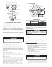
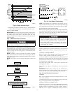
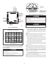
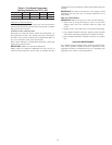
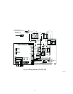
Fig. 12—Control Board
A01192
Defrost Time
Selectors
Thermostat
Low Voltage
Connector
Reserved for
Future Use
Crankcase Heater
Connection
O.D.F. Connection
To Run
Capacitor
Thermistor
Connection
High Pressure
Switch Connector
Low Pressure
Switch Connector
Low/High Speed
Contactor
Connection
Reversing Valve
Connection
CEBD430439-03A
SS0ID
PL1 PL2
HP/AC
C
SEV
RVS
C
HI
LO
PL3
PL4
PL5
OCT OAT HPS LPS
PWM2
PWM1
BRN
BLU
BLK
YEL
RED
CCH L2 ODF VH VC
HK38EA001
K1
CEPL130439-01
COMM STATUS
D51
D52
A B C D
0
Y2
Y1
W1
C
R
120
30
60
60
30
90
DEFROST
TIME (MIN)
R39
R44
R42
C18
C16
R36
FORCED
DEFROST
1
1
1
S1
R89
R91
R87R86
R85
J1
C31
R61
R65
R38
R33
C2
R9
1 2
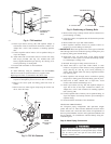
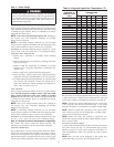
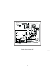
Fig. 13—Resistance Values Versus Temperature
A91431
0
10
20
30
40
50
60
70
80
90
0 20 40 60 80 100 120
TEMPERATURE (DEG. F)
RESISTANCE (KOHMS)
THERMISTOR CURVE
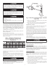
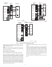
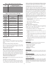
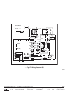
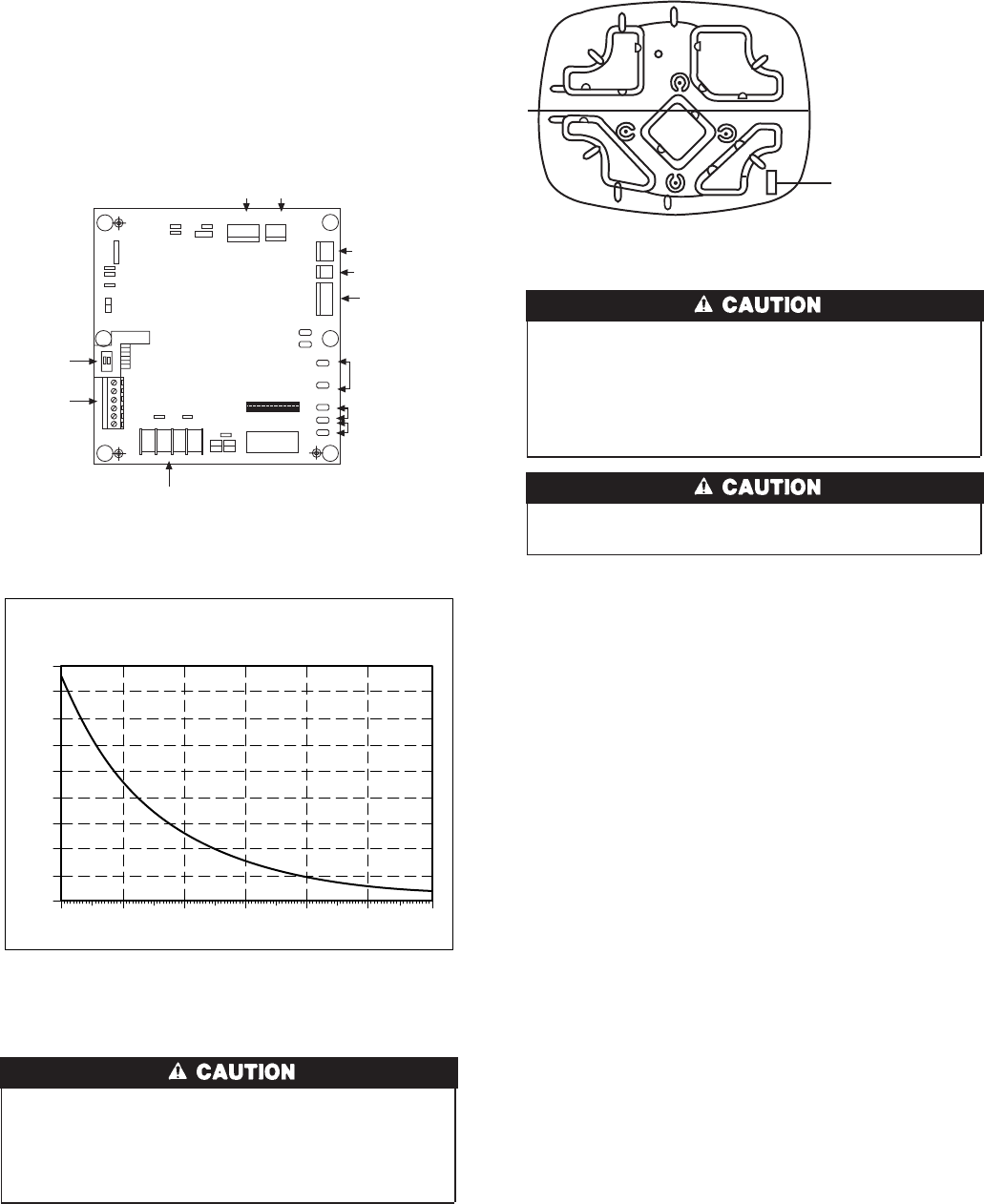
Fig. 14—View from Top of Base Pan
A00430
THERMISTOR PLACED
UNDERNEATH BASE PAN
(ATTACHED TO BASE PAN
WITH ADHESIVE)
Control Box
Side of Unit
10