


8. Install vapor elbow (see Fig. 5B) with equalizer adapter to
suction tube of line set and suction connection to indoor coil.
Adapter has a 1/4-in. male connector or attaching equalizer
tube.
9. Connect equalizer tube of TXV to 1/4-in. equalizer fitting on
vapor line adapter.
10. Attach TXV bulb to horizontal section of suction line using
bulb straps provided. (See Fig. 5C.) Insulate bulb with
factory-supplied insulation tape. (See Fig. 5E.) See Fig. 6 for
correct positioning of sensing bulb.
11. Proceed with remainder of unit installation.
FAN COIL
To obtain efficiency rating for 38TDB037 with FV4ANB006
fancoil TXV must be replaced with factory supplied TXV.
Replacing R-22 TXV or Non-Balance Port Puron TXV
1. Remove any existing refrigerant and ensure coil has not been
exposed to atmospheric pressure for more than 15 minutes.
2. Remove coil access panel and fitting panel from front of
cabinet.
3. Remove and save TXV support clamp using the 5/16-in. nut
driver. Save the clamp.
4. Remove TXV using a backup wrench on flare connections to
prevent damage to tubing.
5. Using wire cutters, cut equalizer tube off flush with vapor tube
inside cabinet.
6. Remove bulb from vapor tube inside cabinet.
7. Braze equalizer stub-tube closed. Use protective barrier as
necessary to prevent damage to drain pan.
IMPORTANT: Route the equalizer tube of the approved Puron®
TXV through suction line connection opening in fitting door prior
to replacing fitting panel around tubing.
8. Install TXV (Fig. 5A) with 3/8-in. copper tubing through
small hole in service panel. Use wrench and backup wrench,
to avoid damage to tubing valve.
9. Reinstall TXV support clamp (removed in item 3).
10. Attach TXV bulb to vapor tube inside cabinet, in same
location as original was when removed, using supplied bulb
straps. (See Fig. 5C.) See Fig. 6 for correct positioning of
sensing bulb. Insulate bulb with factory-supplied insulation
tape. (See Fig. 5E.)
11. Route equalizer tube through suction connection opening
(large hole) in fitting panel and install fitting panel in place.
12. Sweat inlet of TXV, marked “IN” to liquid line. Avoid
excessive heat which could damage valve.
13. Install vapor elbow (see Fig. 5B) with equalizer adapter to
vapor line of line set and vapor connection to indoor coil.
Adapter has a 1/4-in. male connector for attaching equalizer
tube. (See Fig. 5B.)
14. Connect equalizer tube of TXV by 1/4-in. equalizer fitting, on
vapor line adapter. Use backup wrench to prevent damage to
equalizer fitting.
15. Proceed with the remainder of unit installation.
LONG-LINE APPLICATIONS
For refrigerant piping arrangements with equivalent lengths
greater than 50 ft or when elevation difference between indoor
and/or outdoor unit is more than 20 ft, follow all requirements of
the Long-Line Guideline section in the Application Guideline and
Service Manual—Air Conditioners and Heat Pumps Using Pu-
ron® Refrigerant.
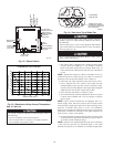
Step 6—Make Piping Connections
Relieve pressure and recover all refrigerant before system
repair or final unit disposal to avoid personal injury or death.
Use all service ports and open all flow-control devices,
including solenoid valves.
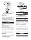
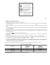
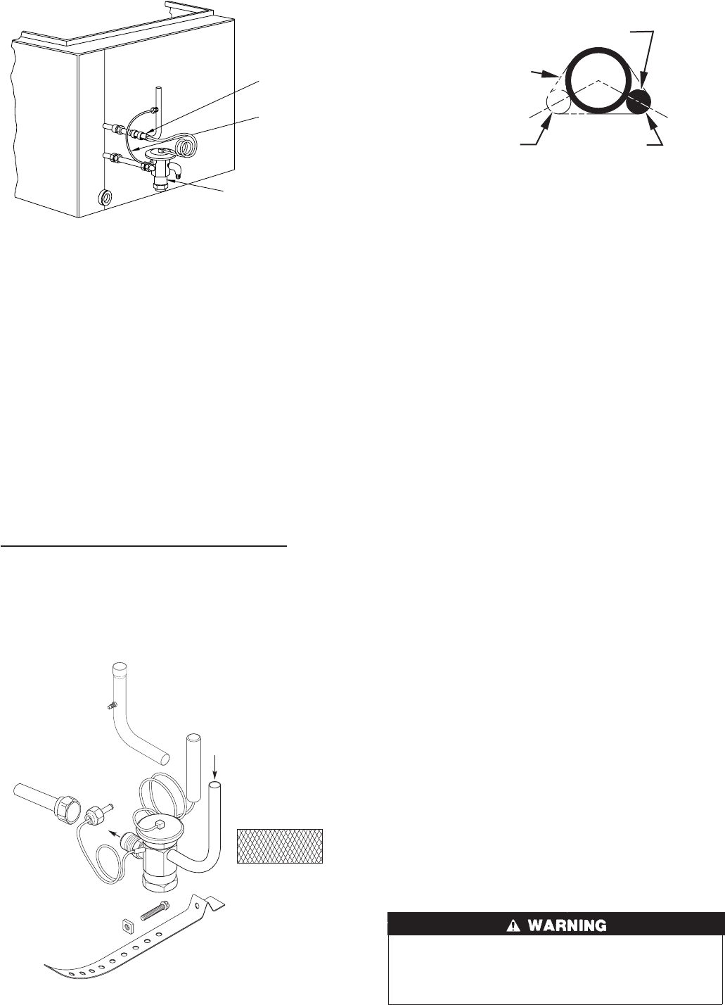
Fig. 4—TXV Installed
A91277
THERMOSTATIC
EXPANSION
VALVE
EQUALIZER
TUBE
SENSING
BULB
COIL
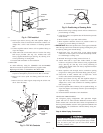
Fig. 5—TXV Kit Contents
A01418
A
B
D
INLET
COIL
E
BULB
INSULATION
TAPE
C
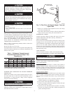
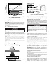
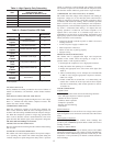
Fig. 6—Positioning of Sensing Bulb
A00399
SENSING BULB
STRAP
8 O'CLOCK
4 O'CLOCK
3
→
→
→
→