


required. The LCC for standard PSC blower products consists of a
standard humidistat which opens contacts on humidity rise and a
pilot duty relay with 24v coil.
NOTE: If an LCC is desired, low-speed airflow must be main-
tained so that a minimum of 300 CFM/ton can be supplied during
high speed LCC operation.
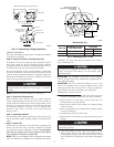
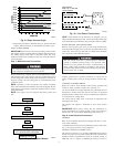
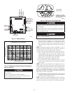
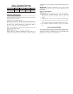
Step 9—Make Airflow Selections
AIRFLOW SELECTION FOR 58CVA/58MVP FURNACES
The 58CVA/58MVP Non-Condensing Variable Speed Furnaces
provide high- and low-speed blower operation to match the
capacities of the compressor at high and low speeds. To select the
recommended airflow and for adjustments to the manual switches
labeled SW1, A/C and CF on the control board refer to the furnace
Installation, Start-Up, and Operating Instructions. The 315AAV
utilizes a control center that allows the installing technician to
select the proper airflows. The A/C switch determines the airflow
during high speed compressor operation. Airflow for hight and low
speed can be calculated at either 350 CFM per ton or 400 CFM per
ton based on the positions of SW1-5.
AIRFLOW SELECTION FOR FK4C, FV4A, OR 40FK FAN
COILS
The FK4C and FV4A provide high- and low-speed blower
operation to match the capacities of compressor at high and low
speeds. To select recommended airflow, refer to the FK4C, FV4A,
or 40FK Installation Instructions. The FK4C, FV4A, and 40FK
utilize an EASY SELECT control board that allows the installing
technician to select proper airflows. For adjustments to control
board and recommended A/C SIZE and CFM ADJUST selections.
This fan coil has an adjustable blower off delay factory set at 90
sec for high- and low-speed blower operation.
For other combinations of equipment consult the Product Data
Digest.
24 VAC HOT
FAN
COOL STAGE 1
COOL STAGE 2
HEAT STAGE 1
HEAT STAGE 2
R
G
R
G
24 VAC COMM
N/A
OUTDOOR
SENSOR
CONNECTION
C
B
S1
S2
C C
R
PROGRAMMABLE
THERMOSTAT
MODEL 2S
FK4C, FV4A
OR 40FK
FAN COIL
J1
JUMPER
REMOVE
J2 JUMPER
FOR HEAT
STAGING
TWO-SPEED
AIR CONDITIONER
DH
Y1
Y1
W/W1
O/W2
Y1/W2
W1
Y/Y2
Y2Y/Y2
O
W2
See notes 1, 2, 3, 5, and 7
A01493
O/W2
W/W1
Y1/W2
G
R
PROGRAMMABLE
THERMOSTAT
MODEL 2S
VARIABLE-SPEED
CONDENSING
FURNACE
TWO-SPEED
AIR CONDITIONER
W/W1
G
Y/Y2
C
Y2
R
Y1
C
B
S1
S2
W2
R
C
HEAT STAGE 1
COOL STAGE 1
COOL STAGE 2
HEAT STAGE 2
FAN
24 VAC HOT
24 VAC COMM
N/A
OUTDOOR
SENSOR
CONNECTION
Y/Y2
HUM
DEHUM
DE
JUMPER
See notes 1, 2, 3, and 5
A01507
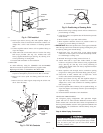
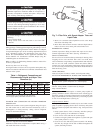
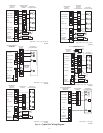
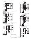
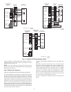
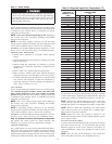
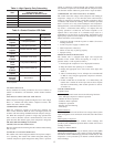
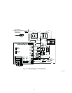
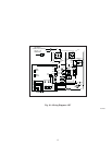
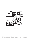
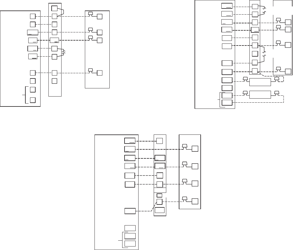
Fig. 11—Typical 24V Wiring Diagram (Cont)
O/W2
W/W1
Y1/W2
G
R
W2
W1
THERMIDISTAT
CONTROL
MODEL RH
FK4C, FV4A
OR 40FK
FAN COIL
TWO-SPEED
AIR CONDITIONER
Y1
G
C
Y2
R
Y1
C
DHUM
HUM
B
S1
S2
Y/Y2
R
O
C
DH
HEAT STAGE 2
HEAT STAGE 1
COOL STAGE 1
COOL STAGE 2
FAN
24 VAC HOT
24 VAC COMM
DEHUMIDIFY
HUMIDIFY
N/A
OUTDOOR
SENSOR
CONNECTION
Y/Y2
HUMIDIFIER
(24 VAC)
OUTDOOR
SENSOR
REMOVE J2 JUMPER
FOR HEAT STAGING
REMOVE
J1 JUMPER
See notes 1, 2, 3, 6, 7, 8, and 9
A01494
8