


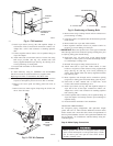
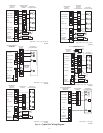
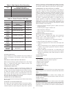
5. Repeat this procedure as indicated in Fig. 9. System will then
contain minimal amounts of contaminants and water vapor.
FINAL TUBING CHECK
IMPORTANT: Check to be certain factory tubing on both indoor
and outdoor unit has not shifted during shipment. Ensure tubes are
not rubbing against each other or any sheet metal. Pay close
attention to feeder tubes, making sure wire ties on feeder tubes are
secure and tight.
Step 7—Make Electrical Connections
To avoid personal injury or death, do not supply power to unit
with compressor terminal box cover removed.
Be sure field wiring complies with local and national fire, safety,
and electrical codes, and voltage to system is within limits shown
on unit rating plate. Contact local power company for correction of
improper voltage. See unit rating plate for recommended circuit
protection device.
NOTE: Operation of unit on improper line voltage constitutes
abuse and could affect unit reliability. See unit rating plate. Do not
install unit in system where voltage may fluctuate above or below
permissible limits.
NOTE: Use copper wire only between disconnect switch and
unit.
NOTE: Install branch circuit disconnect of adequate size per
NEC to handle unit starting current. Locate disconnect within sight
from and readily accessible from unit, per Section 440-14 of NEC.
ROUTE GROUND AND POWER WIRES
Remove access panel to gain access to unit wiring. Extend wires
from disconnect through power wiring hole provided and into unit
control box. Size wires per NEC but not smaller than minimum
wire size shown in Product Data Digest.
The unit cabinet must have as uninterrupted or unbroken
ground to minimize personal injury if an electrical fault
should occur. The ground may consist of electrical wire or
metal conduit when installed in accordance with existing
electrical codes. Failure to follow this warning can result in an
electric shock, fire, or death.
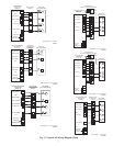
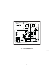
CONNECT GROUND AND POWER WIRES
Connect ground wire to ground connection in control box for
safety. Connect power wiring to leads provided as shown in Fig.
10.
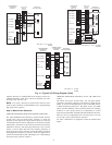
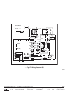
CONNECT CONTROL WIRING
Route 24v control wires through control wiring grommet and
connect to leads provided in control box. (See Fig. 11.)
Use No. 18 AWG color-coded, insulated (35°C minimum) wire. If
thermostat is located more than 100 ft from unit, as measured
along the control voltage wires, use No. 16 AWG color-coded wire
to avoid excessive voltage drop.
All wiring must be NEC Class 1 and must be separated from
incoming power leads.
The outdoor unit requires a minimum of 27va, 24vac control
power.
IMPORTANT: Check factory wiring and wire connections to
ensure terminations are secured properly. Check wire routing to
ensure wires are not in contact with tubing, sheet metal, etc.
Step 8—Install Electrical Accessories
GENERAL
Refer to the individual instructions packaged with kits or acces-
sories when installing.
Available electrical accessories include latent capacity control. See
Fig. 11 for typical accessory wiring diagrams.
LATENT CAPACITY CONTROL (LCC)
The purpose of an LCC is to provide a dehumidification mode to
assure a 75 percent or less system sensible heat ratio. If indoor unit
installed contains an ECM blower (such as an FK4C, FV4A, or
40FK fan coil or a 58CVA or 58MVP gas furnace), no LCC is
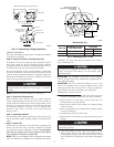
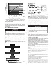
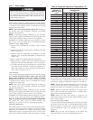
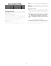
Fig. 8—Deep Vacuum Graph
A95424
500
MINUTES
01234567
1000
1500
LEAK IN
SYSTEM
VACUUM TIGHT
TOO WET
TIGHT
DRY SYSTEM
2000
MICRONS
2500
3000
3500
4000
4500
5000
A95424
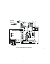
CHECK FOR TIGHT, DRY SYSTEM
(IF IT HOLDS DEEP VACUUM)
EVACUATE
BREAK VACUUM WITH DRY NITROGEN
WAIT
EVACUATE
CHARGE SYSTEM
BREAK VACUUM WITH DRY NITROGEN
EVACUATE
WAIT
A95425
Fig. 9—Triple Evacuation Method
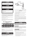
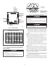
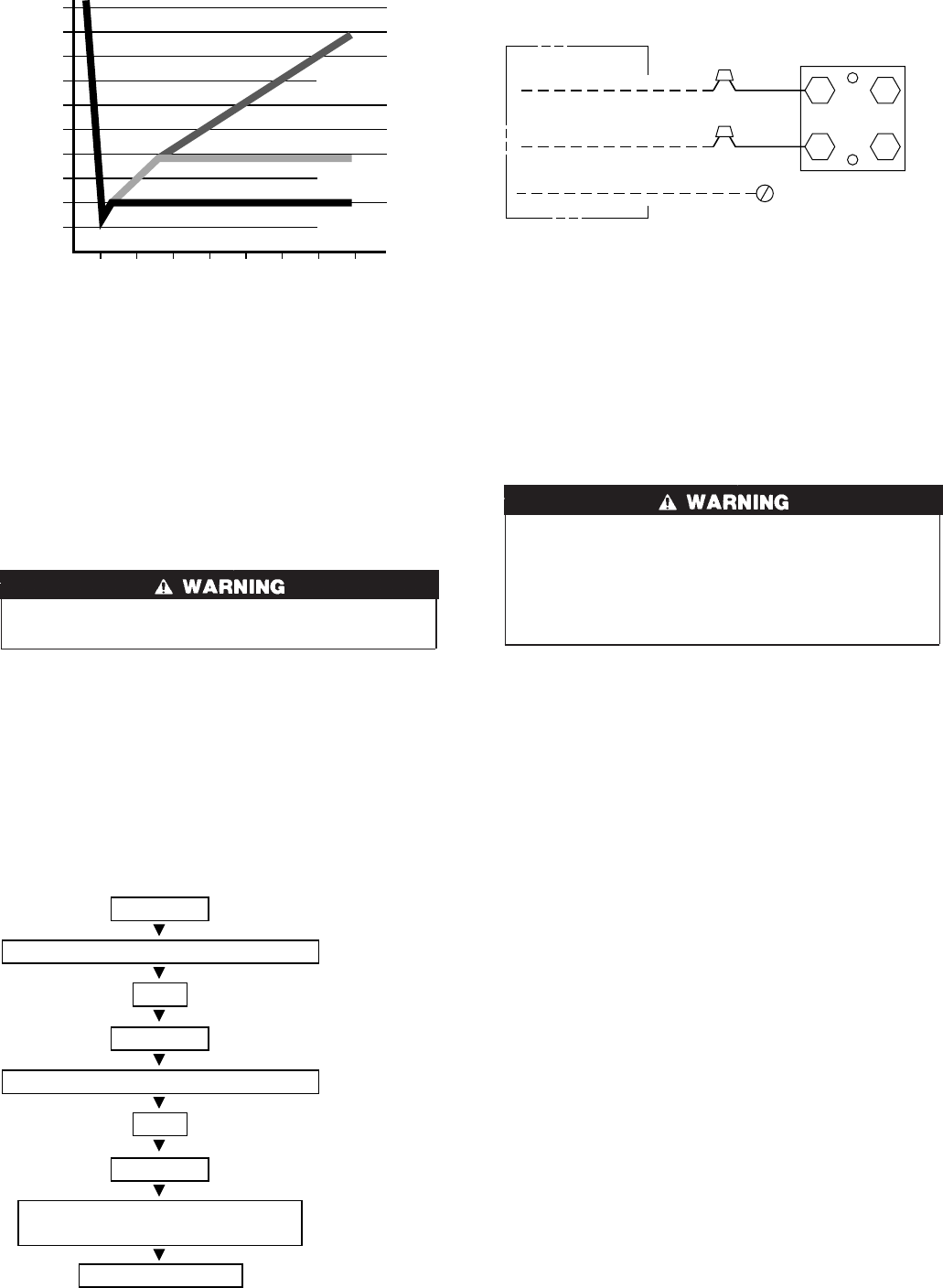
Fig. 10—Line Power Connections
A91306
CONTACTOR
DISCONNECT
PER N. E. C. AND/ OR
LOCAL CODES
FIELD POWER
WIRING
FIELD GROUND
WIRING
GROUND
LUG
5