


Step 11—Check Charge
Service valve gage ports are not equipped with Schrader
valves. To prevent personal injury, make sure gage manifold
is connected to the valve gage ports before moving valves off
fully back seated position. Wear safety glasses and gloves
when handling refrigerant.
UNIT CHARGE
Factory charge and charging method are shown on pink charging
label. With unit operating, charge Puron® units with liquid using
a commercial type metering device in manifold hose. Charge
refrigerant into suction line.
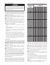
NOTE: Unit is to be charged in high capacity only. Charging in
low capacity may cause compressor chattering and possible
damage to the compressor.
NOTE: If subcooling charging conditions are not favorable,
charge must be weighed in accordance with unit rating plate ± 0.6
oz/ft of 3/8-in. liquid line above or below 15 ft respectively.
EXAMPLE: To calculate additional charge required for a 25-ft
line set: 25 ft - 15 ft = 10 ft X 0.6 oz/ft=6ozofadditional charge.
COOLING ONLY PROCEDURE
1. Operate unit a minimum of 15 minutes before checking
charge.
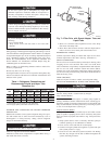
2. Measure liquid service valve pressure by attaching an accurate
gage to service port.
3. Measure liquid line temperature by attaching an accurate
thermistor type or electronic thermometer to liquid line near
outdoor coil.
4. Refer to Table 4 for required subcooling temperature.
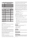
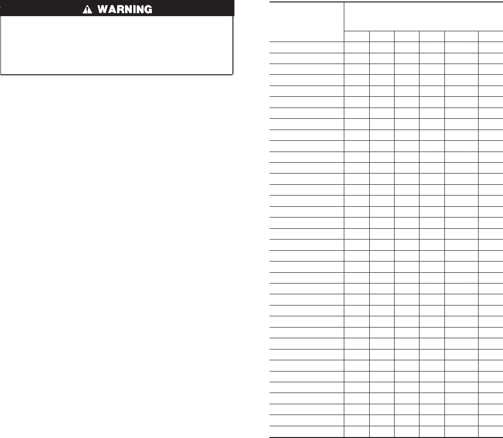
5. Refer to Table 3. Find the point where required subcooling
temperature intersects measured liquid service valve pressure.
6. To obtain required subcooling temperature at a specific liquid
line pressure, add refrigerant if liquid line temperature is
higher than indicated or reclaim refrigerant if temperature is
lower. Allow a tolerance of ± 3°F.
.
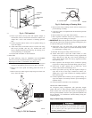
UNIT CHARGE
Factory charge and charging method are shown on pink charging
label. Puron® refrigerant cylinders contain a dip tube which
allows liquid refrigerant to flow from cylinder in upright
position. Charge Puron units with cylinder in upright position and
a commercial type metering device in manifold hose. Charge
refrigerant into suction line.
NOTE: Unit is to be charged in high capacity only. Charging in
low capacity may cause compressor chattering and possible
damage to the compressor.
NOTE: If subcooling charging conditions are not favorable,
charge must be weighed in accordance with unit rating plate ± 0.6
oz/ft of 3/8-in. liquid line above or below 15 ft respectively.
EXAMPLE: To calculate additional charge required for a 25 ft line
set: 25 ft - 15 ft = 10 ft x 0.6 oz/ft=6ozofadditional charge.
Step 12—System Functions and Sequence of Operation
The outdoor unit control system has special functions. The
following is an overview of the two-speed control functions:
COOLING OPERATION
This product utilizes a 2-stage cooling indoor thermostat. With a
call for first stage cooling (Yl), the outdoor fan and low capacity
compressor are energized. If low capacity cannot satisfy cooling
demand, high capacity is energized (Yl and Y2 or Y2 only) by the
second stage of indoor thermostat. After second stage is satisfied,
the unit returns to low-speed operation until first stage is satisfied
or until second stage is required again. When both first stage and
second stage cooling are satisfied, the compressor will shut off.
NOTE: If unit has not operated within the past 12 hr, or following
a unit power-up, upon the next thermostat high- or low-speed
demand, unit operates for a minimum of 5 minutes on high-speed.
NOTE: When two-speed unit is operating at low speed, system
vapor (suction) pressure will be higher than a standard single-
speed system or high-speed operation.
NOTE: Outdoor fan motor will continue to operate for one
minute after compressor shuts off, when outdoor ambient is greater
than or equal to 100°F.
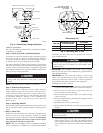
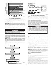
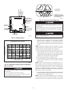
STATUS FUNCTION LIGHTS
A system control STATUS function light is located on the outdoor
unit control board. (See Fig. 12.) The STATUS light provides
indication signals for several system operations. See Table 5 for
codes and definitions. Table 5 also provides the order of signal
importance.
NOTE: Only one code will be displayed on the outdoor unit
control board (the most recent, with the highest priority).
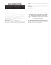
Table 3—Required Liquid-Line Temperature (°F)
LIQUID
PRESSURE AT
SERVICE VALVE
(PSIG)
REQUIRED SUBCOOLING
TEMPERATURE
(°F)
8 121416 18 18
189 58 56 54 52 50 48
195 60 58 56 54 52404 50
202 62 60 58 56 54 52
208 64 62 60 58 56 54
215 66 64 62 60 58 56
222 68 66 64 62 60 58
229 70 68 66 64 62 60
236 72 70 68 66 64 62
243 74 72 70 68 66 64
251 76 74 72 70 68 66
259 78 76 74 72 70 68
266 80 78 76 74 72 70
274 82 80 78 76 74 72
283 84 82 80 78 76 74
291 86 84 82 80 78 76
299 88 86 84 82 80 78
308 90 88 86 84 82 80
317 92 90 88 86 84 82
326 94 92 90 88 86 84
335 96 94 92 90 88 86
345 98 96 94 92 90 88
354 100 98 96 94 92 90
364 102 100 98 96 94 92
374 104 102 100 98 96 94
384 106 104 102 100 98 96
395 108 106 104 102 100 98
406 110 108 106 104 102 100
416 112 110 108 106 104 102
427 114 112 110 108 106 104
439 116 114 112 110 108 106
450 118 116 114 112 110 108
462 120 118 116 114 112 110
474 122 120 118 116 114 112
486 124 122 120 118 116 114
499 126 124 122 120 118 116
511 128 126 124 122 120 118
11