


INSPECT EQUIPMENT
File claim with shipping company prior to installation if shipment
is damaged or incomplete.
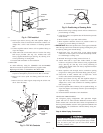
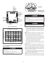
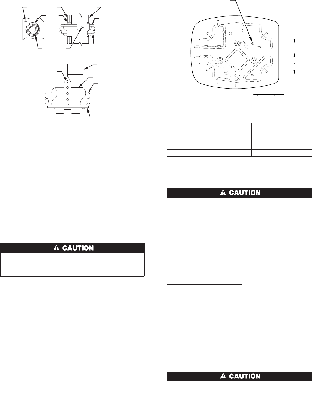
Step 2—Install on a Solid, Level Mounting Pad
If conditions or local codes require the unit be attached to pad, tie
down bolts should be used and fastened through knockouts
provided in unit base pan. Refer to unit mounting pattern in Fig. 3
to determine base pan size and knockout hole location.
On rooftop applications, mount on level platform or frame. Place
unit above a load bearing wall and isolate unit and tubing set from
structure. Arrange supporting members to adequately support unit
and minimize transmission of vibration to building. Consult local
codes governing rooftop applications.
Do not allow POE lubricant to come into contact with roofing
material. POE may deteriorate certain types of synthetic
roofing.
NOTE: Unit must be level to within ±2° (±3/8 in./ft).
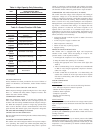
Step 3—Clearance Requirements
When installing, allow sufficient space for airflow clearance,
wiring, refrigerant piping, and service. Allow 30-in. clearance to
service end of unit and 48 in. above unit. For proper airflow, a 6-in.
clearance on 1 side of unit and 12 in. on all remaining sides must
be maintained. Maintain a distance of 24 in. between units.
Position so water, snow, or ice from roof or eaves cannot fall
directly on unit.
Step 4—Operating Ambient
The minimum outdoor operating ambient in cooling mode is 55°F,
and the maximum outdoor operating ambient in cooling mode is
125°F.
Step 5—Install TXV
Puron® fan coils and furnace coils come factory equipped with a
bi-flow, hard shut off TXV specifically designed for Puron®
two-speed units. No TXV changeout is required. An existing R-22
TXV must be replaced with a factory approved TXV specifi-
cally designed for Puron® two-speed units.
NOTE: FK4, FC4, and 40FK fan coils are equipped with an R-22
TXV. If an FK4, FC4, or 40FK fan coil is used with a Puron® air
conditioner, the R-22 TXV must be replaced with a factory-
approved Puron® TXV.
If indoor unit is equipped with piston, remove indoor coil
piston and replace with balance port hard shutoff TXV
metering device.
IMPORTANT: The 38TDB037 unit includes a factory supplied
TXV kit. All other sizes do not include factory supplied TXV kit.
TXV INSTALLATION
IMPORTANT: The TXV should be mounted as close to the
indoor coil as possible and in a vertical, upright position. Avoid
mounting the inlet tube vertically down. A factory supplied or
approved filter drier must be installed in the liquid line.
Installing TXV in Place of Piston
1. Remove any existing refrigerant and ensure coil has not been
exposed to atmospheric pressure for more than 15 minutes.
2. Remove indoor coil inlet tube at piston body inlet. Use
back-up wrench to prevent damage.
3. Remove piston retainer, begin careful not to damage scaling
surface of O-ring.
4. Remove and discard factory-installed piston. (Replace retainer
if O-ring is damaged.)
5. Reinstall piston retainer in piston body.
6. Replace indoor coil inlet tube. Use back-up wrench to prevent
damage.
To prevent damage to the unit, use a brazing shield and wrap
TXV with wet cloth.
7. Sweat swivel adapter (see Fig. 5D) to inlet of indoor coil and
attach to TXV (see Fig. 5A) outlet. Use backup wrench to
avoid damage to tubing or valve. Sweat Inlet of TXV, marked
“IN” to liquid line. Avoid excessive heat which could damage
valve
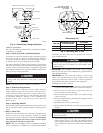
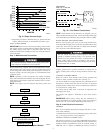
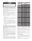
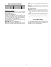
Fig. 2—Connecting Tubing Installation
A01383
INSULATION
VAPOR TUBE
LIQUID TUBE
OUTDOOR WALL INDOOR WALL
LIQUID TUBE
VAPOR TUBE
INSULATION
CAULK
Avoid contact between tubing and structureNOTE:
THROUGH THE WALL
HANGER STRAP
(AROUND VAPOR
TUBE ONLY)
JOIST
1″ MIN.
SUSPENSION
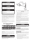
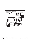
Fig. 3—Mounting Unit to Pad
Dimensions (In.)
UNIT SIZE
MINIMUM MOUNTING
PAD DIMENSIONS
TIEDOWN KNOCKOUT
LOCATIONS
AB
024 19 X 24 2-13/16 6-15/16
036-060 26 X 32 4 9-3/4
A97548
C
L
A
B
VIEW FROM TOP
8
3
/
16
″
3
/8-IN. DIA TIEDOWN
KNOCKOUTS IN BASEPAN
(2) PLACES
2
→
→
→
→