


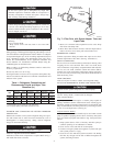
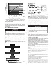
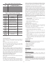
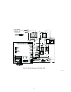
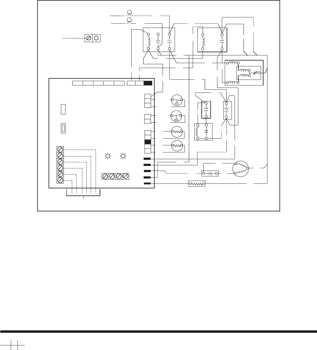
→ Fig. 17—Wiring Diagram—060
A02212
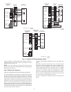
CONNECTION DIAGRAM
OCT
-t∞
LPS
HPS
OAT
-t∞
LOHI
TO INDOOR UNIT
RED
CCH
FAN CAP
RED
BRN
OFM
BLK
BLU/PNK
BLU/PNK
YEL/PNK
YEL/PNK
BRN
BRN
BLK
RED
BLU
CH
11
2123
13
YEL
BLK
BLK
H
C
START
COMP
RELAY
BRN
CAP
L2
L1
EQUIP GND
DUAL CAPACITY
ABCD
BLU
BRN
BLK
YEL
BRN
BLK
C
O
W
Y
2
Y
1
R
1
RVSSEVHP/AC CC
VH
L 2
ODF
CCH
VC
12345
PL1
12
PL2
1
2
3
1
2
1
2
4
5
YEL
BLU
BLK
BRN
BRN
1
2
YEL
5
BRN
BLU
STAR
T
CAP
CL
11
21
208 / 230 - 1- 60
POWER SUPPLY
COMM STATUS
FORCED
DEFROST
TIME (MIN)
DEFROST
PL5
PL4
PL3
BLU
YEL
BRN
YEL
RED
BLK
BLK
LPS
HPS
OAT
OCT
COMP
YEL
R
S
C
NOTE #11
BLU
BLU
BL
U
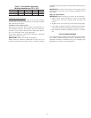
Copyright 2002 CARRIER Corp. • 7310 W. Morris St. • Indianapolis, IN 46231 38tdb4si
Manufacturer reserves the right to discontinue, or change at any time, specifications or designs without notice and without incurring obligations.
Book 1 4
Tab 3a 2a
PC 101 Catalog No. 533-80059 Printed in U.S.A. Form 38TDB-4SI Pg 16 8-02 Replaces: 38TDB-3SI