


FACTORY DEFAULTS
Factory defaults have been provided in the event of failure of
outdoor air thermistor, coil thermistor, and/or furnace interface
jumper.
ONE MINUTE SPEED CHANGE TIME DELAY
When compressor changes speeds from high to low or low to high,
there is a 1-minute time delay before compressor restarts. The
outdoor fan motor remains running.
COMPRESSOR OPERATION
When the compressor operates in second stage operation, the
motor rotates clockwise. Both the lower and upper pistons are
eccentric with the rotating crankshaft and both compress refriger-
ant. When the compressor operates in single stage operation the
motor reverses direction (rotates counterclockwise). The lower
piston becomes idle and the upper piston compresses refrigerant.
The start and run windings are reversed.
CRANKCASE HEATER OPERATION
The two-speed control board energizes the crankcase heater during
unit off cycle.
OUTDOOR FAN MOTOR OPERATION
The outdoor unit control energizes outdoor fan any time compres-
sor is operating. The outdoor fan remains energized during the
1-minute compressor speed change time delay and if a pressure
switch or compressor overload should open. Outdoor fan motor
will continue to operate for one minute after the compressor shuts
off when the outdoor ambient is greater than or equal to 100°F.
COMPRESSOR VOLTAGE FAILURE (6 FLASHES)
The control senses the voltage of the compressor run winding. If
compressor voltage (Vc) is less than 90v when control board is
calling for compressor operation, control shuts compressor off for
15 minutes with outdoor fan running. After 15 minutes (provided
there is a call for Y1 or Y2), control attempts to start compressor.
During this time, a code of 6 flashes appears at control board. If Vc
trip occurs 3 consecutive times during a Y1 request, then low
capacity operation is locked out and control responds to Y2
requests until a reset occurs. If 3 consecutive trips occur in a
combination of Yl and Y2 or all Y2 requests, then both low and
high capacity operation will be locked out. The compressor voltage
failure (6 flashes) can be caused by:
• compressor internal overload trip (refer to Table 6 for correct
winding resistance)
• no 240 volt power supply to outdoor unit
• failed compressor contactor(s)
• failure of start relay to pick-up properly
• improper wiring
PRESSURE SWITCH PROTECTION
The outdoor unit is equipped with high- and low-pressure
switches. If the control senses the opening of a high or low
pressure switch, it will respond as follows:
1. De-energize the compressor low or high speed contactor,
2. Keep the outdoor fan operating for 15 minutes,
3. Display the appropriate error code on the status light. (See
Table 5)
4. After a 15 minute delay, if Yl or Y2 inputs are on and the LPS
or HPS is reset, energize appropriate compressor contactor,
either low or high.
5. If LPS or HPS has not closed after a 15 minute delay, the
outdoor fan is turned off. If the open switch closes anytime
after the 15-minute delay, then resume operation on call for
Y1 and/or Y2.
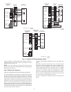
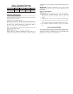
MAJOR COMPONENTS
2-Speed Control
The two-speed control board controls the following functions:
- Low- and high-compressor contactor operation
- Outdoor fan motor operation
- Crankcase heater operation
- Compressor protection
- Pressure switch monitoring
- Time delays
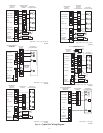
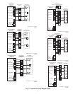
Field Connections
The two-speed control received 24vac low-voltage control system
inputs through the screw connections on the left side of the control
board.
Dual Capacity Compressor
The dual capacity compressor contains motor windings that
provide 2-pole (3500 RPM) operation. Refer to Table 6 for correct
winding resistance.
Compressor Internal Relief
The compressor is protected by an internal pressure relief (IPR)
which relieves discharge gas into compressor shell when differen-
tial between suction and discharge pressures exceeds 525 psi. The
compressor is also protected by an internal overload attached to
motor windings.
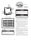
Table 4—High Capacity Only Subcooling
UNIT
TXV TYPE EXPANSION DEVICE
HIGH CAPACITY ONLY
SUBCOOLING AT SERVICE VALVE
024 14°F
036 15°F
037 11°F
048 12°F
060 16°F
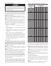
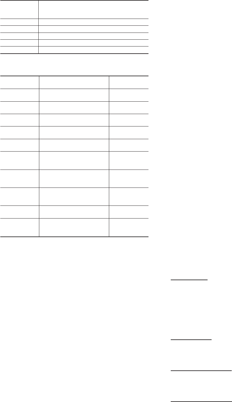
Table 5—Control Function LED Code
CODE DEFINITION
SIGNAL
IMPORTANCE*
Constant flash
No pause
No demand
Stand by
10
1 flash
w/pause
Low-speed operation 9
2 flashes
w/pause
High-speed operation 8
3 flashes
w/pause
Outdoor thermistor failure 7
4 flashes
w/pause
Outdoor coil thermistor failure 6
3 flashes
pause
4 flashes
Thermistor out of range 5
5 flashes
pause
1 flash
Low pressure switch trip 4
5 flashes
pause
2 flashes
High pressure switch trip 3
6 flashes
w/pause
Compressor V
C
/V
H
trip 2
Constant light
No pause
No flash
Board failure 1
*Function light signal order of importance in case of multiple signal request; 1
is most important.
12