


Do not leave system open to atmosphere any longer than
minimum required for installation. POE oil in compressor is
extremely susceptible to moisture absorption. Always keep
ends of tubing sealed during installation.
If ANY refrigerant tubing is buried, provide 6–in. vertical rise
at service valve. Refrigerant tubing lengths up to 36 in. may
be buried without further special consideration. Do not bury
lines for lengths over 36 in.
To prevent damage to unit or service valves, observe the
following:
• Use a brazing shield.
• Wrap service valves with wet cloth or use a heat sink
material.
Outdoor units may be connected to indoor section using accessory
tubing package or field-supplied refrigerant grade tubing of correct
size and condition. Tubing diameters listed in Table 1 are adequate
for equivalent lengths up to 50 ft. For tubing requirements beyond
50 ft, substantial capacity and performance losses will occur.
Follow the recommendations in the Application Guideline and
Service Manual—Air Conditioners and Heat Pumps Using Pu-
ron® Refrigerant to minimize losses.
Refer to Table 1 for field tubing diameters. Refer to Table 2 for
accessory requirements.
Do not bury lines over 36 in. long.
If refrigerant tubes or indoor coil are exposed to atmosphere, they
must be evacuated to 500 microns to eliminate contamination and
moisture in the system.
OUTDOOR UNIT CONNECTED TO FACTORY-APPROVED
INDOOR UNIT
Outdoor unit contains correct system refrigerant charge for opera-
tion with indoor unit of same size when connected by 15 ft of
field-supplied or factory-accessory tubing. Check refrigerant
charge for maximum efficiency
Installation of filter drier in liquid line is required.
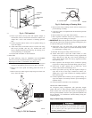
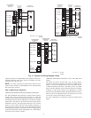
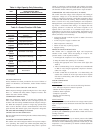
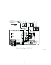
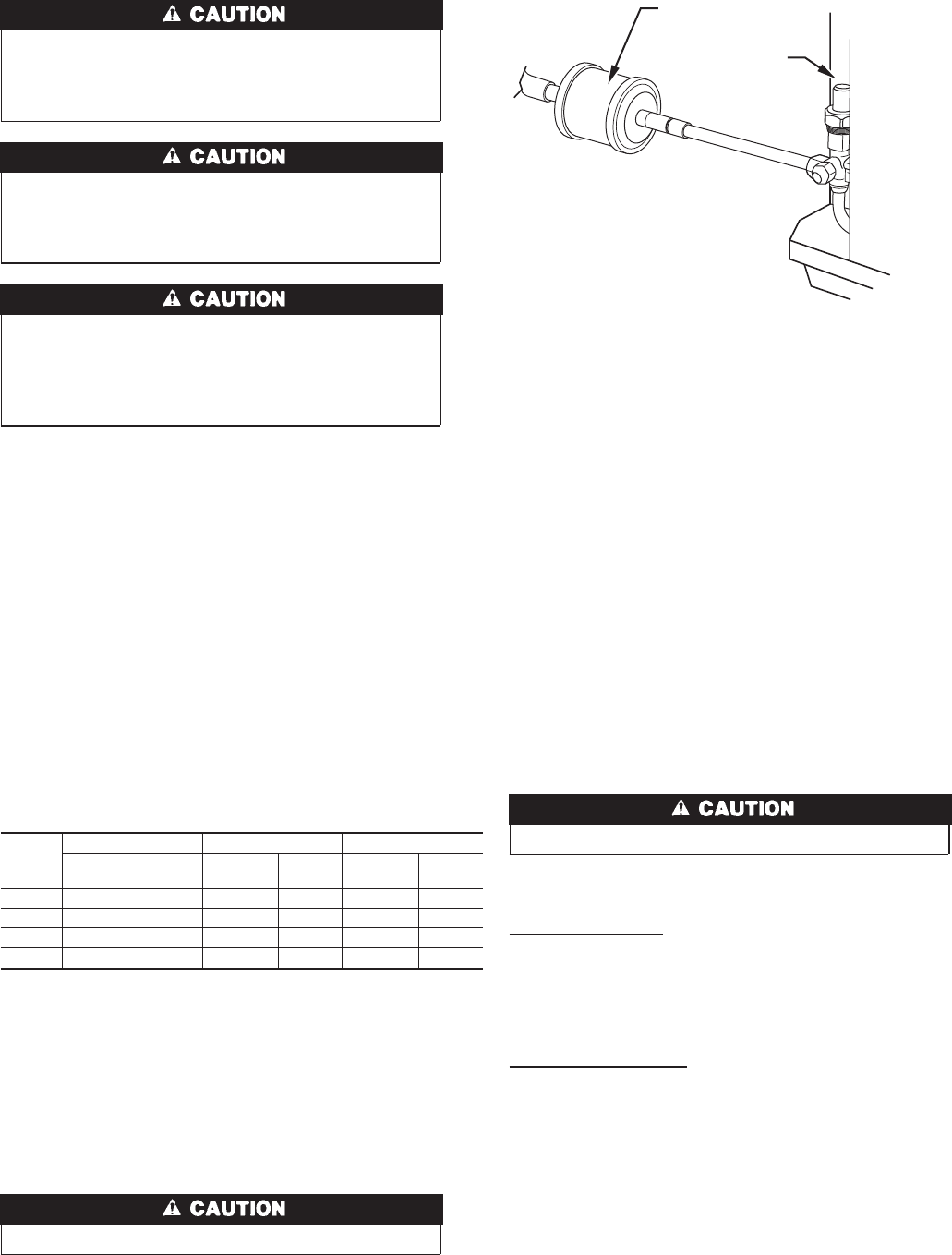
INSTALL LIQUID-LINE FILTER DRIER
Installation of filter drier in liquid line is required. Refer to Fig. 7
and install filter drier as follows:
1. Braze 5–in. connector tube to liquid line service valve. Wrap
filter drier with damp cloth.
2. Braze filter drier between connector tube and liquid tube to
indoor coil. Flow arrow must point toward indoor coil.
REFRIGERANT TUBING
Connect vapor tube to fitting on outdoor unit vapor service valves.
Connect liquid tube to filter drier. (See Fig. 7and Table 1.)
SWEAT CONNECTION
Service valves are closed from factory and ready for brazing. After
wrapping service valve and filter drier with a wet cloth, braze
sweat connections using industry accepted methods and materials.
Do not use soft solder (materials which melt below 800°F).
Consult local code requirements. Refrigerant tubing and indoor
coil are now ready for leak testing. This check should include all
field and factory joints.
LEAK CHECKING
Leak test all joints in indoor, outdoor, and refrigerant tubing.
EVACUATE REFRIGERANT TUBING AND INDOOR COIL
Never use the system compressor as a vacuum pump.
Refrigerant tubes and indoor coil should be evacuated to 500
microns. Always break a vacuum with dry nitrogen.
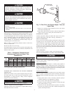
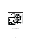
Deep Vacuum Method
The deep vacuum method requires a vacuum pump capable of
pulling a minimum vacuum of 500 microns and a vacuum gage or
thermistor capable of accurately measuring this vacuum depth. The
deep vacuum method is the most positive way of assuring a system
is free of air and liquid water. (See Fig. 8.)
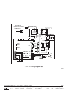
Triple Evacuation Method
The triple evacuation method should only be used when vacuum
pump is capable of pumping down to 28 in. of mercury and system
does not contain any liquid water. Refer to Fig. 9 and proceed as
follows:
1. Pump system down to 28 in. of mercury and allow pump to
continue operating for an additional 15 minutes.
2. Close service valves and shut off vacuum pump.
3. Connect a nitrogen cylinder and regulator to system and open
until system pressure is 2 psig.
4. Close service valve and allow system to stand for 1 hr. During
this time, dry nitrogen will be able to diffuse throughout the
system, absorbing moisture.
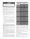
Table 1—Refrigerant Connections and
Recommended Liquid and Vapor Tube
Diameters (In.)
UNIT
SIZE
LIQUID VAPOR VAPOR (LONG-LINE)
Connection
Diameter
Tube
Diameter
Connection
Diameter
Tube
Diameter
Connection
Diameter
Tube
Diameter
024 3/8 3/8 5/8 5/8 5/8 3/4
036 3/8 3/8 3/4 3/4 3/4 7/8
037, 048 3/8 3/8 7/8 7/8 7/8 7/8
060 3/8 3/8 7/8 1-1/8 7/8 1-1/8
Notes:
1. Tube diameters are for lengths up to 50 equivalent ft.
2. Do not apply capillary tube indoor coils to these units.
Fig. 7—Filter Drier with Sweat Adapter Tube and
Liquid Tube
A01215
LIQUID
SERVICE
VALVE
LIQUID-LINE
FILTER-DRIER
4