


5-16
Cisco MGX Route Processor Module (RPM-PR) Installation and Configuration Guide
Release 2.1, Part Number 78-12510-02 Rev. C1, August 31, 2004
Chapter 5 Configuring the MGX RPM-PR
Establishing 1:N Redundancy Between Two or More RPM-PR Cards
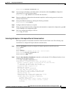
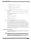
.!!!!
Success rate is 80 percent (4/5), round-trip min/avg/max = 1/1/1 ms
Router#
If the connection fails, verify that you have the correct IP address for the remote device and that the
remote device is active (powered on). Then repeat the ping command.
Establishing 1:N Redundancy Between Two or More RPM-PR
Cards
RPM-PR cards support 1:N redundancy, whereby one RPM-PR card can be configured as a redundant
or secondary (backup) card for one or multiple primary RPM-PR cards, forming a redundant group.
There can be multiple redundant groups in one shelf. RPM-PR 1:N redundancy is a cold redundancy, in
which the configuration of a failed primary card is copied to the standby secondary card. All traffic to
and from the primary RPM-PR card is switched to the secondary card after it becomes active. Because
this is a cold redundancy solution, service interruption is expected. As with other service modules, the
layer 2 state is restored when the secondary card becomes active. However, RPM-PR also performs layer
3 functionality, such as maintaining routing tables. The routing tables are created manually or by routing
protocols, such as IGRP, BGP, or OSPF. Because routing protocols are used, the layer 3 state is restored
within three to five minutes, depending on the protocol used.
RPM-PR 1:N redundancy supports the following features:
• Increases availability by decreasing the DPM of the network by reducing boot-up, switchover, and
upgraded times.
• Supports L2 redundancy and restores L3 state via reconvergence.
• Support for up to 11 active (primary) RPM-PRcards per single redundant (standby or secondary)
RPM-PR.
• Support for a maximum of 6 redundant groups per MGX 8850 or MGX 8950.
The redundant card must be present and active and must not have any connections configured. Any
connection configuration will cause the addred command to be rejected.
To establish a backup card for an RPM-PR card, use the following procedure.
Step 1 Logon to the switch.
Step 2 If you have not done so already, initialize both cards as described earlier in this chapter in “Initializing
the RPM-PR Card.”
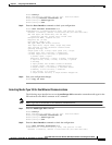
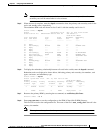
Step 3 Enter the dspcds command to verify that the primary and secondary RPM-PR card are in the “Active”
state.
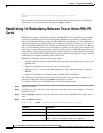
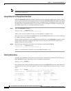
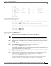
Step 4 Enter the addred command.
Switch.7.PXM.a > addred <redPrimarySlotNum> <redSecondarySlotNum> <redType>
Parameter Description
<redPrimarySlotNum> Slot number of the primary RPM-PR card.
<redSecondarySlotNum> Slot number of the secondary RPM-PR card.
<redType> 2 for 1:n redundancy.
Note 1 is for 1:1 redundancy which is not supported.