


1-19
Cisco ASR 9001 and Cisco ASR 9001-S Routers Hardware Installation Guide
OL-26701-02
Chapter 1 Preparing for Installation
Site Requirement Guidelines
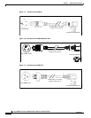
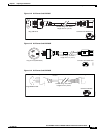
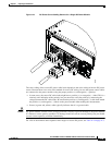
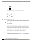
Figure 1-21 DC Power Source Cabling Scheme for a Single DC Power Module
The color coding of the source DC power cable leads depends on the color coding of the site DC power
source. Because there is no color code standard for source DC wiring, be sure that power source cables
are connected to the power modules using the proper positive (+) and negative (–) polarity:
• In some cases, the source DC cable leads might have a positive (+) or a negative (–) label. This is a
relatively safe indication of the polarity, but you must also verify the polarity by measuring the
voltage between the DC cable leads. Be sure that the positive (+) and negative (–) cable leads match
the positive (+) and negative (–) labels on the power module when making the measurement.
• Green (or green and yellow) cable typically indicates that it is a ground cable.
Caution DC power modules contain reverse voltage protection circuitry to prevent damage to the power module
if it detects a reverse polarity condition. No damage should occur from reverse polarity, but you should
correct a reverse polarity condition immediately.
For a list of the nominal and acceptable value ranges for source DC power, see Table A-4 on page A-3.
331933