


1-4
Cisco Aironet 1100 Series Access Point Hardware Installation Guide
OL-4309-07
Chapter 1 Overview
Hardware Features
LEDs
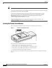
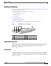
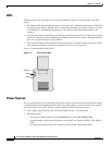
The three LEDs on the top of the access point report Ethernet activity, association status, and radio
activity.
• The Ethernet LED signals Ethernet traffic on the wired LAN, or Ethernet infrastructure. This LED
is normally green when an Ethernet cable is connected, and blinks green when a packet is received
or transmitted over the Ethernet infrastructure. The LED is off when the Ethernet cable is not
connected.
• The status LED signals operational status. Steady green indicates that the access point is associated
with at least one wireless client. Blinking green indicates that the access point is operating normally
but is not associated with any wireless devices.
• The radio LED signals wireless traffic over the radio interface. The light is normally off, but it blinks
green whenever a packet is received or transmitted over the access point radio.
Figure 1-2 shows the three status LEDs.
Figure 1-2 Access Point LEDs
Power Sources
The access point draws up to 4.9W of DC power and can receive power from an external power module
or through inline power using the Ethernet cable. Using inline power, you do not need to run a separate
power cord to the access point. The access point supports the following power sources:
• Power supply (input 100–240 VAC, 50–60 Hz, output 48 VDC, 0.2A minimum)
• Inline power from:
–
Cisco Aironet Power Injector (Cisco AIR-PWRINJ3= or Cisco AIR-PWRINJ-FIB= )
–
A switch capable of providing inline power, such as the Cisco Catalyst 3500XL, 3550, 4000, or
6500
–
An inline power patch panel, such as the Cisco Catalyst Inline Power Patch Panel
Ethernet
Status
Radio
81597