


2-4
Cisco Aironet 1100 Series Access Point Hardware Installation Guide
OL-4309-07
Chapter 2 Installing the Access Point
Basic Installation Guidelines
Access Point Layout and Connectors
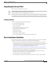
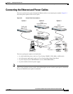
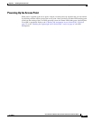
Figure 2-1 shows the access point layout and connectors.
Figure 2-1 Access Point Layout and Connectors
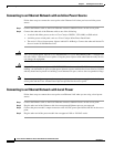
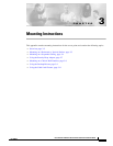
LEDs
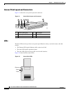
The three LEDs on the top of the access point report Ethernet activity, association status, and radio
activity.
• The Ethernet LED signals Ethernet traffic on the wired LAN.
• The status LED signals operational status.
• The radio LED signals wireless traffic over the radio interface.
Figure 2-2 shows the three status LEDs.
Figure 2-2 Access Point LEDs
1 2 3 5
81180
6
4
1 48-VDC power port 4 Mode button
2 Ethernet port (RJ-45) 5 Status LEDs
3 Cable lock slot 6 Antenna
Ethernet
Status
Radio
81597