


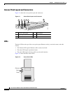

2-7
Cisco Aironet 1100 Series Access Point Hardware Installation Guide
OL-4309-07
Chapter 2 Installing the Access Point
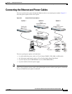
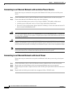
Connecting the Ethernet and Power Cables
Connecting the Ethernet and Power Cables
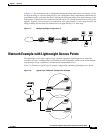
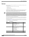
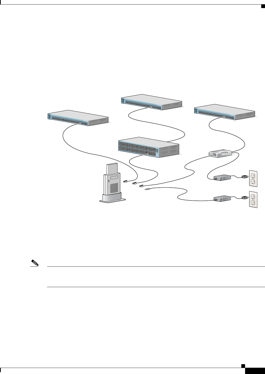
The access point receives power through the Ethernet cable or an external power module. Figure 2-3
shows the power options for the access point.
Figure 2-3 Access Point Power Options
The access point power options are listed below:
• A switch with inline power, such as a Cisco Catalyst 3500XL, 3550, 4000, or 6500 switch
• An inline power patch panel, such as a Cisco Catalyst Inline Power Patch Panel
• A power injector (Cisco AIR-PWRINJ3= or Cisco AIR-PWRINJ-FIB= )
• A power module (Universal power supply)
Note If you use in-line power from a switch or patch panel, do not connect the power module to the access
point. Using two power sources on the access point might cause the switch or patch panel to shut down
the port to which the access point is connected.
Power
cord
Universal
power supply
S
Y
S
T
R
P
S
D
U
P
L
X
M
O
D
E
S
P
E
E
D
U
T
IL
S
T
A
T
1
2
3
4
5
6
7
8
9
10
1
1
1
2
1
3
1
4
1
5
1
6
1
7
1
8
19
2
0
2
1
2
2
2
3
2
4
2
3
2
4
10B
ase
-T / 100B
ase
-T
X
100B
as
e-FX
Catalyst 2950
S
E
R
IE
S
S
Y
S
T
R
P
S
D
U
P
L
X
M
O
D
E
S
P
E
E
D
U
T
IL
S
T
A
T
1
2
3
4
5
6
7
8
9
1
0
1
1
1
2
1
3
14
1
5
1
6
1
7
1
8
1
9
2
0
2
1
2
2
23
2
4
2
3
2
4
10
B
ase-T
/ 100B
ase-T
X
10
0
Base-F
X
Catalyst 2950
S
E
R
IE
S
S
Y
S
T
R
P
S
D
U
P
L
X
M
O
D
E
S
P
E
E
D
U
T
IL
S
T
A
T
1
2
3
4
5
6
7
8
9
1
0
1
1
1
2
1
3
1
4
1
5
16
1
7
1
8
1
9
2
0
2
1
2
2
2
3
2
4
23
2
4
10B
ase
-T
/ 100B
ase-T
X
10
0B
ase-FX
Catalyst 2950
S
E
R
IE
S
S
Y
S
T
R
P
S
D
U
P
L
X
M
O
D
E
S
P
E
E
D
U
T
IL
S
T
A
T
TO
AP/ BRIDGE
TO
NETWORK
Switch with
inline power
Power injector
Access Point
Switch
(without inline power)
Switch
(without inline power)
Inline Power
Patch Panel
Option 1 Option 2 Option 3
Option 4
81596
81173