


5-13
Cisco 3600 Series Hardware Installation Guide
OL-2056-02
Chapter 5 Installing Memory in the Router
Replacing DRAM and SDRAM
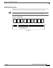
Installing DRAM SIMMs
Perform this procedure to install DRAM SIMMs:
Step 1 Attach an ESD-preventive wrist strap and ensure that it makes good contact with your skin. Connect the
equipment end of the wrist strap to the metal back plate of the chassis, avoiding contact with the
connectors.
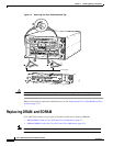
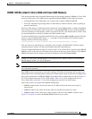
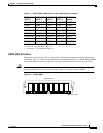
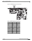
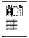
Step 2 On the mainboard, locate the DRAM SIMM sockets shown in Figure 5-5 or Figure 5-6.
Caution Handle SIMMs by the edges only. SIMMs are ESD-sensitive components and can be damaged by
mishandling.
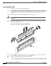
Step 3 Hold the SIMM with the polarization notch on the right, near the front of the chassis, and with the
connector edge at the bottom.
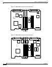
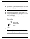
Step 4 Beginning with bank 0, insert the SIMM into the socket at an angle, tilted toward the right side of the
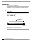
chassis. Rock the SIMM into a vertical position (see Figure 5-9), using the minimum amount of force
required. When the SIMM is properly seated, the socket guide posts fit through the alignment holes, and
the locking spring clips click into place.
Step 5 Ensure that each SIMM is straight (perpendicular to the socket), and that the alignment holes (as shown
in Figure 5-9) line up with the plastic socket guides on the socket.
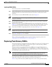
Figure 5-9 Installing DRAM SIMMs
Caution It is normal to feel some resistance when installing a SIMM, but do not use excessive force on the
SIMM, and do not touch the surface components.
Step 6 Repeat Step 3 through Step 5 for each SIMM.
When you finish replacing SIMMs, proceed to the “Replacing the Cover on a Cisco 3620 or Cisco 3640
Router” section on page 5-30.
H7037
1. Insert the SIMM into the socket
at an angle from vertical.
The socket guide posts fit through
the holes in the SIMM.
3.
The locking springs clip the back
of the SIMM.
4.
View from front of chassis
2. Push the top of the SIMM
down and back.