


5-5
Cisco 3600 Series Hardware Installation Guide
OL-2056-02
Chapter 5 Installing Memory in the Router
Accessing the Mainboard
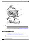
Removing the Cisco 3660 Mainboard Tray
Note In this publication, references to Cisco 3660 routers include both Cisco 3661 and Cisco 3662 models.
Use the following procedure to remove the mainboard tray:
Step 1 Power OFF the router. However, to channel ESD voltages to ground, do not unplug the power cable.
Warning
Before opening the chassis, disconnect the telephone-network cables to avoid contact with
telephone-network voltages. To see translations of the warnings that appear in this publication,
refer to the
Regulatory Compliance and Safety Information
document that accompanied this
device.
Step 2 Remove all network interface cables from the mainboard tray’s rear panel.
Step 3 Place the router so that the rear panel is facing you.
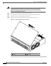
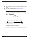
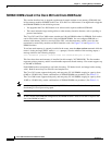
There are two sets of screws on the mainboard rear panel: one set of captive screws, and one set of Torx
screws. (See Figure 5-4.)
Caution Do not remove or loosen the Torx screws.
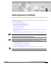
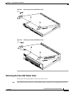
Step 4 Loosen the two captive screws located in the upper corners. (See part 1, Figure 5-4.)
Step 5 Swing the two tray levers out, and slide the mainboard tray out of the chassis. (See parts 2 and 3,
Figure 5-4.)