


5-20
Cisco 3600 Series Hardware Installation Guide
OL-2056-02
Chapter 5 Installing Memory in the Router
Replacing Flash Memory SIMMs
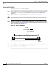
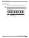
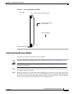
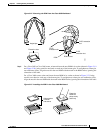
Flash memory SIMMs have a polarization notch to ensure proper orientation and alignment holes to
ensure proper positioning, similar to that shown in Figure 5-7. Flash memory SIMMs are installed with
the connector edge down and the polarization notch near the front of the chassis.
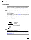
Caution To avoid damaging ESD-sensitive components, observe all ESD precautions. To avoid damaging the
underlying mainboard, do not use excessive force when you remove or replace SIMMs.
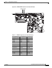
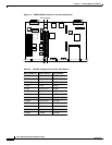
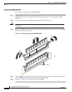
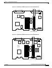
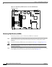
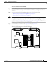
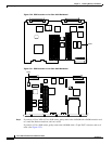
Figure 5-14, Figure 5-15, and Figure 5-16 show the location of the Flash memory SIMMs on your
router’s mainboard.
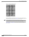
Table 5-6 Flash Memory SIMM Configurations
Bank 0 Bank 1 Total Memory
4 MB – 4 MB
4 MB 4 MB 8 MB
4 MB 8 MB 12 MB
4 MB 16 MB 20 MB
8 MB – 8 MB
8 MB 4 MB 12 MB
8 MB 8 MB 16 MB
8 MB 16 MB 24 MB
16 MB – 16 MB
16 MB 4 MB 20 MB
16 MB 8 MB 24 MB
16 MB 16 MB 32 MB
32 MB 32 MB 64 MB
1
1. The 64 MB configuration is only available on the
Cisco 3660 router.