


5-2
Cisco 3600 Series Hardware Installation Guide
OL-2056-02
Chapter 5 Installing Memory in the Router
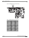
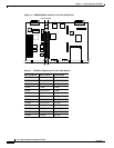
Accessing the Mainboard
Accessing the Mainboard
This section describes how to open the system in order to access the router’s internal components such
as memory modules and the ROM. You need a number 2 Phillips or flat-blade screwdriver to perform
this procedure.
Warning
Do not touch the power supply when the power cord is connected. For systems with a power
switch, line voltages are present within the power supply even when the power switch is OFF and
the power cord is connected. For systems without a power switch, line voltages are present
within the power supply when the power cord is connected. To see translations of the warnings
that appear in this publication, refer to the
Regulatory Compliance and Safety Information
document that accompanied this device.
Warning
Before performing any of the following procedures, ensure that power is removed from the DC
circuit. To ensure that all power is OFF, locate the circuit breaker on the panel board that services
the DC circuit, switch the circuit breaker to the OFF position, and tape the switch handle of the
circuit breaker in the OFF position. To see translations of the warnings that appear in this
publication, refer to the
Regulatory Compliance and Safety Information
document that
accompanied this device.
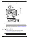
Removing the Cisco 3620 or Cisco 3640 Router Cover
Use the following procedure to remove the cover:
Step 1 Power OFF the router. However, to channel ESD voltages to ground, do not unplug the power cable.
Warning
Before opening the chassis, disconnect the telephone-network cables to avoid contact with
telephone-network voltages. To see translations of the warnings that appear in this publication,
refer to the
Regulatory Compliance and Safety Information
document that accompanied this
device.
Step 2 Remove all network interface cables from the rear panel.
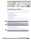
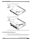
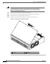
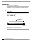
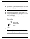
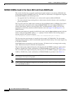
Step 3 Place the router so that the front panel is facing you. Remove the three screws located on top of the cover
near the front edge. (See Figure 5-1 or Figure 5-2.) Set the screws aside in a safe place.
Step 4 Lift the front edge of the cover until it clears the front of the chassis. (See Figure 5-1 or Figure 5-2.)
Step 5 Pull the cover toward you until the metal tabs on the rear edge separate from the chassis bottom. (See
Figure 5-1 or Figure 5-2.)
Step 6 Lift the cover until it is free from the chassis and set it aside.
When you are ready to replace the cover, see the “Replacing the Cover on a Cisco 3620 or Cisco 3640
Router” section on page 5-30.