


19
PA-4R Half-Duplex Token Ring Port Adapter Installation and Configuration
OL-3589-01
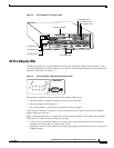
VIP2 and the 4R Port Adapter
Configuring the 4R Interfaces
The following procedures describe basic configuration information for the 4R port adapter. If you
installed a new 4R port adapter or if you want to change the configuration of an existing interface, you
must enter configuration mode using the configure command. If you replaced a 4R port adapter that was
previously configured, the system will recognize the new 4R interfaces and bring them up in their
existing configuration.
After you verify that the new 4R port adapter is installed correctly (the enabled LED goes on), use the
privileged-level configure command to configure the new interfaces. Be prepared with the information
you will need, such as the following:
• Protocols you plan to route on each new interface
• Internet protocol (IP) addresses if you plan to configure the interfaces for IP routing
• Whether the new interfaces will use bridging
Note The 4R interfaces on a VIP2 can be configured for 16-Mbps operation and are configured for 4-Mbps
operation as a default.
For a summary of the configuration options available and instructions for configuring the 4R interfaces
on the VIP2, refer to the appropriate configuration publications listed in the section “If You Need More
Information” on page 2.
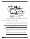
Determining Chassis Slot, Port Adapter, and Token Ring Interface Port Numbers
The following section describes how to identify chassis slot, port adapter, and Token Ring interface port
numbers.
Note Although the processor slots in the seven-slot Cisco 7507 and 13-slot Cisco 7513 are vertically oriented
and those in the five-slot Cisco 7505 are horizontally oriented, all models use the same method for slot
and port numbering.
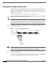
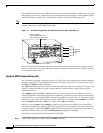
In the router, physical port addresses specify the actual physical location of each interface port on the
router interface processor end. (See .) This address is composed of a three-part number in the format
chassis slot number/port adapter number/interface port number, as follows:
• The first number identifies the chassis slot in which the VIP2 is installed (as shown in the example
system in ).
• The second number identifies the physical port adapter number on the VIP2, and is either 0 or 1.
• The third number identifies interface ports on each 4R port adapter and are always numbered in
sequence as interface 0 through 3.
Interface ports on the 4R port adapter maintain the same address regardless of whether other interface
processors are installed or removed. However, when you move a VIP2 to a different slot, the first number
in the address changes to reflect the new slot number.
shows some of the slot port adapter and interface ports of a sample Cisco 7505 system. The first port
adapter slot number is always 0. The second port adapter slot number is always 1. The individual
interface port numbers always begin with 0. The number of additional ports depends on the number of
ports on a port adapter.