


6
PA-4R Half-Duplex Token Ring Port Adapter Installation and Configuration
OL-3589-01
Port Adapter Installation Prerequisites
Preventing Electrostatic Discharge Damage
Electrostatic discharge (ESD) damage, which can occur when electronic cards or components are
improperly handled, results in complete or intermittent failures. Port adapters and processor modules
consist of printed circuit boards that are fixed in metal carriers. Electromagnetic interference (EMI)
shielding and connectors are integral components of the carrier. Although the metal carrier helps to
protect the board from ESD, use a preventive antistatic strap during handling.
Following are guidelines for preventing ESD damage:
• Always use an ESD wrist or ankle strap and ensure that it makes good skin contact.
• Connect the equipment end of the strap to an unfinished chassis surface.
• When installing a component, use any available ejector levers or captive installation screws to
properly seat the bus connectors in the backplane or midplane. These devices prevent accidental
removal, provide proper grounding for the system, and help to ensure that bus connectors are
properly seated.
• When removing a component, use any available ejector levers or captive installation screws to
release the bus connectors from the backplane or midplane.
• Handle carriers by available handles or edges only; avoid touching the printed circuit boards or
connectors.
• Place a removed component board-side-up on an antistatic surface or in a static shielding container.
If you plan to return the component to the factory, immediately place it in a static shielding
container.
• Avoid contact between the printed circuit boards and clothing. The wrist strap only protects
components from ESD voltages on the body; ESD voltages on clothing can still cause damage.
• Never attempt to remove the printed circuit board from the metal carrier.
Caution For safety, periodically check the resistance value of the antistatic strap. The measurement should be
between 1 and 10 megohms.
Token Ring Overview
The following sections describe Token Ring specifications, physical connections, connection equipment,
and cables and connectors.
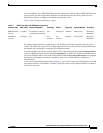
Token Ring Specifications
The term Token Ring refers to both IBM’s Token Ring Network, which IBM developed in the 1970s, and
to IEEE 802.5 networks. The IEEE 802.5 specification was modeled after, and still closely shadows,
IBM’s network. The two types are compatible, although the specifications differ slightly.
Token Ring and IEEE 802.5 are token passing networks, which move a small frame, called a token,
around the network. Possession of the token grants the right to transmit; a station with information to
transmit must wait until it detects a free token passing by.
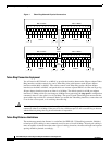
The IBM Token Ring specifies a star topology, with all end stations connected through a device called a
multistation access unit (MSAU). IEEE 802.5 does not specify any topology, although most
implementations are based on a star configuration with end stations attached to a device called a media