


EN
ENGLISH
Clarke
®
Operator's Manual (EN) - DC Propane Burnisher - 15 -
Maintenance And Adjustments
Emission Control Information
To protect the environment in which we will live, the
manufacturer has incorporated crankcase emission (1) and
exhaust emission (2) control systems (EM) in compliance
with applicable regulations of the United States Environ-
mental Protection Agency and California Air Resources
Board.
1.
Crankcase Emission Control System -
A sealed-type
crankcase emission control system is used to eliminate
blow-by gases. The blow-by gases are led to the
breather chamber through the crankcase. Then, it is led
to the air cleaner. Oil is separated from the gases while
passing through the inside of the breather chamber
from the crankcase, and then returned back to the
bottom of crankcase.
2.
Exhaust Emission Control System -
The exhaust
emission control system applied to this engine consists
of a carburetor and an ignition system having optimum
ignition timing characteristics. The carburetor has been
calibrated to provide lean air/fuel mixture characteristics
and optimum fuel economy with a suitable air cleaner
and exhaust system.
Tampering w/Emission Control System Prohibited
Federal law and California State law prohibits the following
acts or the causing thereof: (1) the removal or rendering
inoperative by any person other than for purposes of
maintenance, repair, or replacement, of any device or
element of design incorporated into any new engine for the
purpose of emission control prior to its sale or delivery to
the ultimate purchaser or while it is in use, or (2) the use of
the engine after such device or element of design has been
removed or rendered inoperative by any person.
Among those acts presumed to constitute tampering are the
acts listed below:
Do not tamper with the original emission related part.
>Carburetor and internal parts
>Spark plugs
>Magneto or electronic ignition system
>Fuel filter element
>Air cleaner elements
>Crankcase
>Cylinder heads
>Breather chamber and internal parts
>Intake pipe and tube
General Maintenance and Adjustments
1.
Fuel Control System -
To ensure personal safety,
adjustments should ONLY be made by a qualified LPG
system technician or an authorized service center,
using an exhaust gas analyzer. Do not operate the
machine if carbon monoxide levels exceed OSHA
standards.
2.
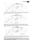
Pad Replacement-
(a) Adjust handle to its extreme upright position (Note:
Pins should be in the hole marked "TILTBACK").
(b) Grabbing the handle with both hands and placing
your foot on the back deck of the burnisher for
stability, pull back on the handle and tilt the
machine back.
(c) Let the handle rest on the floor to hold the machine
in the upright position.
(d) Now move to the pad side of the machine.
(e) Grab the metal clip, which is located in the
white center-lock device, between the thumb
and index finger and squeeze. This allows the
pad retainer to "pop" off.
(f) Remove the old pad.
(g) Install the new pad by carefully centering it
against the "harpoon hook" plastic gripper.
(h) Replace the pad retainer by snapping it back in
place (Note: The center-lock ring should "snap"
twice).
(i) Check the rotation of the pad driver. Eccentric-
ity of the pad should not exceed 1/4 of an inch.
3.
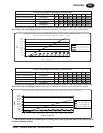
Belt Replacement -
(a) Tilt the machine back as you would to replace
the pad.
(b) Using a 3/4" open-end wrench, secure the shaft
from the engine side of the deck and spin off the
pad driver to remove it.
(c) Use the same 3/4" wrench to release tension on
the belt by rotating the Lovejoy tensioner
towards the belt.
(d) Release the Lovejoy tensioner and carefully
remove the belt from the engine clutch and the
drive pulley.
(e) Now install the new belt onto the clutch and
pulley and use the wrench to again release the
tension on the Lovejoy tensioner until the belt is
in position.
(f) Release the Lovejoy tensioner to apply tension
to the belt. (Note: the arrow on the Lovejoy
tensioner should be pointing towards 30°. If it is
not, reset the tensioner by first loosening and
then re-tightening the bolt that holds the
tensioner to the deck).
(g) Reinstall the pad driver.
4.
Changing the Engine Oil -
(a) Start and warm up the engine so the oil will
drain easily.
(b) Stop the engine.
(c) Place the buffer in a level position.
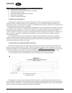
(d) Pull the clear plastic tube out of it's holder and
rotate the tube so that it can drain into a
container.
(e) Grab the 1/4-turn quick release oil drain and
rotate counterclockwise. This will allow the
engine oil to drain.
(f) After draining is complete, rotate the quick
release 1/4-turn clockwise to close and store
the clear plastic tube in it's upright position.
5.
Changing the Oil Filter -
(a) Using either a strap wrench or an oil filter
wrench, rotate the oil filter counterclockwise.
Note: Before unscrewing the oil filter, place a
suitable container beneath the oil drip tray to
catch the oil that is from the filter or any oil
passages in the engine.
(b) Clean the oil filter base on the engine.