


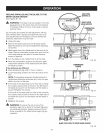
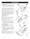
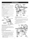
TO ADJUST THE MITER GAUGE
See Figure 53.
You can set the miter gauge at 0° and plus or minus
45° with the miter gauge stop pin and adjustable stop
screws.
NOTE: The miter gauge provides close accuracy in
angled cuts. For very close tolerances, test cuts are
recommended.
[] Loosen knob and pull out on stop pin to rotate miter
gauge base past stop screws.
[] Loosen the lock nut of the 0° stop screw at the stop
pin with a 8 mm wrench.
[] Place a 90° square against the miter gauge rod and
the miter gauge base.
[] If the rod is not square, loosen the knob, adjust the
rod, and tighten the knob.
[] Adjust the 0° stop screw until it rests against the
stop pin.
[] Adjust the plus and minus 45° stop screws using a
45° triangle and the steps above.
MITER
GAUGEBASE
MITER
GAUGEROD
45° ADJUSTABLE
STOPSCREW
LOCK 0° ADJUSTABLE
NUT STOPSCREW
Fig. 53
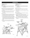
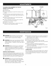
TO SET THE BLADE AT 0° AND 45 °
See Figures 54 - 55.
The angle settings of the saw have been set at the
factory and, unless damaged in shipping, should not re-
quire setting during assembly. After extensive use, they
may need to be checked.
[] Unplug the saw.
[] Raise the blade.
if the blade is not perfectly vertical (0°):
[] Loosen the adjustment screw and the bevel locking
lever.
[] Place a combination square beside the blade on the
left. Lock the angle by pushing the bevel locking
lever down and retighten the adjustment screw.
[] Turn the handle until the bevel indicator points to
zero. If the handle is turned as far as possible and
doesn't indicate zero properly, you may need to
adjust the bevel indicator.
NOTE: It will be necessary to remove the handle to
adjust the bevel indicator.
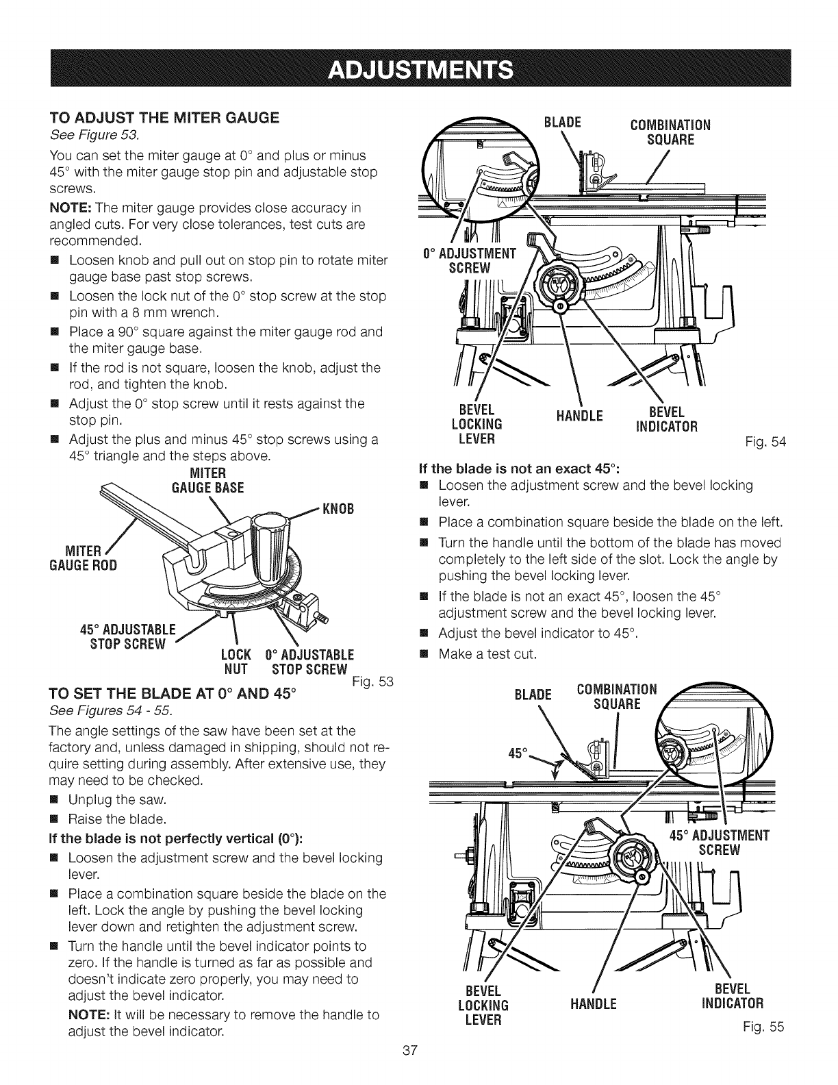
BLADE COMBiNATiON
SQUARE
O°ADJUSTMENT
SCREW
BEVEL HANDLE BEVEL
LOCKING INDICATOR
LEVER Fig. 54
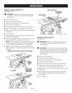
if the blade is not an exact 45°:
[] Loosen the adjustment screw and the bevel locking
lever.
[] Place a combination square beside the blade on the left.
[] Turn the handle until the bottom of the blade has moved
completely to the left side of the slot. Lock the angle by
pushing the bevel locking lever.
[] If the blade is not an exact 45°, loosen the 45°
adjustment screw and the bevel locking lever.
[] Adjust the bevel indicator to 45°.
[] Make a test cut.
BLADE COMBINATION
SQUARE
45° ADJUSTMENT
SCREW
BEVEL BEVEL
LOCKING HANDLE INDICATOR
LEVER
Fig. 55
37